
HVAC Multimeter Guide: How to Use, Test, and Troubleshoot HVAC Systems with a Digital Multimeter
Learn how to use an HVAC multimeter to test voltage, resistance, and continuity. Step-by-step guide for technicians and DIYers troubleshooting heating and... ❓
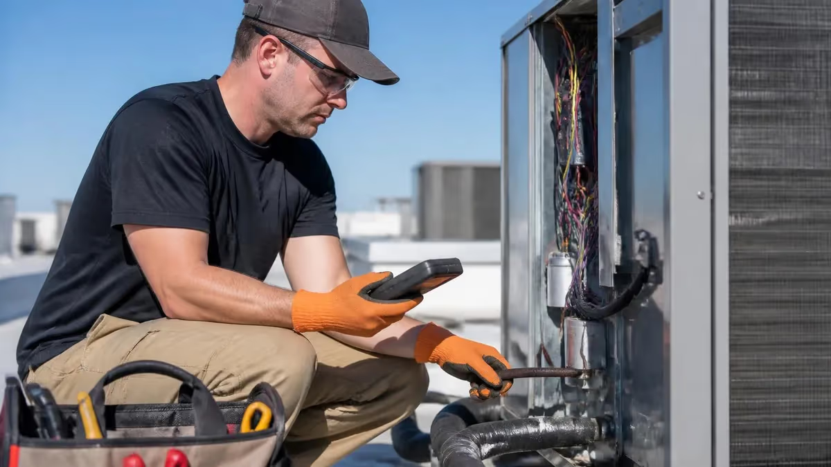
An hvac multimeter is one of the most essential diagnostic tools any heating and cooling technician can carry on a service call. Whether you are chasing a no-heat complaint in the middle of January, diagnosing a compressor that will not start, or verifying that a new thermostat is wired correctly, a quality digital multimeter gives you fast, accurate electrical readings that guide every decision you make on the job. Without it, you are essentially guessing — and guessing costs time, parts, and customer confidence.
A digital multimeter, often abbreviated as a DMM, measures three fundamental electrical properties: voltage, current (amperage), and resistance. Most modern HVAC-grade meters also measure capacitance, temperature via a thermocouple probe, frequency, and diode continuity. These expanded functions make a single instrument capable of diagnosing dozens of different failure modes across furnaces, air conditioners, heat pumps, and commercial rooftop units. Understanding which function to select and how to interpret the reading separates a competent diagnostician from someone who simply replaces parts and hopes for the best.
The HVAC industry runs on electricity. Even a gas furnace relies on 120-volt line power to run its control board, inducer motor, blower motor, gas valve, and igniter. A central air conditioning system uses 240-volt power for the compressor and condenser fan, plus 24-volt low-voltage circuits for control signaling. Heat pumps add reversing valves and defrost controls to the mix. Each of these circuits can fail in a way that is only visible through careful voltage and resistance measurements — the exact thing a quality multimeter is built to provide.
Choosing the right meter for HVAC work matters more than many technicians realize. A basic homeowner meter picked up at a hardware store for fifteen dollars may lack the input protection, true-RMS capability, and measurement range that commercial HVAC circuits demand. Category III and Category IV safety ratings are critical when working near electrical panels and disconnect boxes. True-RMS meters accurately read the non-sinusoidal waveforms produced by variable-frequency drives and electronically commutated motors, which are increasingly common in high-efficiency HVAC equipment. Spending the money on a professional-grade instrument pays for itself on the first complex service call.
Safety is the first principle of multimeter use in HVAC applications. Before taking any measurement, visually inspect the test leads for cracked insulation, loose connectors, or bent probes. Confirm that the meter is set to the correct function and range before touching a live circuit.
Always keep one hand away from the electrical panel when probing — this eliminates the possibility of current traveling across your chest if accidental contact occurs. Lock out and tag out power before performing resistance or continuity tests, since those functions inject their own small current and will give incorrect readings — or be damaged — if external voltage is present.
This guide walks through every major multimeter application you will encounter on an HVAC service call, from reading supply voltage at the disconnect box to measuring microfarads on a run capacitor to checking the resistance of a gas valve coil. Each section explains which meter setting to use, what range to select, where to place the probes, and how to interpret the number that appears on the display. Real-world target values are included wherever possible so you can immediately evaluate whether a reading indicates a healthy circuit or one that needs repair.
Whether you are preparing for your EPA 608 certification, studying for a state HVAC license exam, or simply trying to become more confident and efficient on the job, mastering multimeter techniques is a career-defining skill. The technicians who can read a circuit, understand what the numbers mean, and explain the findings clearly to a customer are the ones who build reputations for excellence, earn higher wages, and advance into lead technician and supervisory roles.
HVAC Multimeter Use by the Numbers
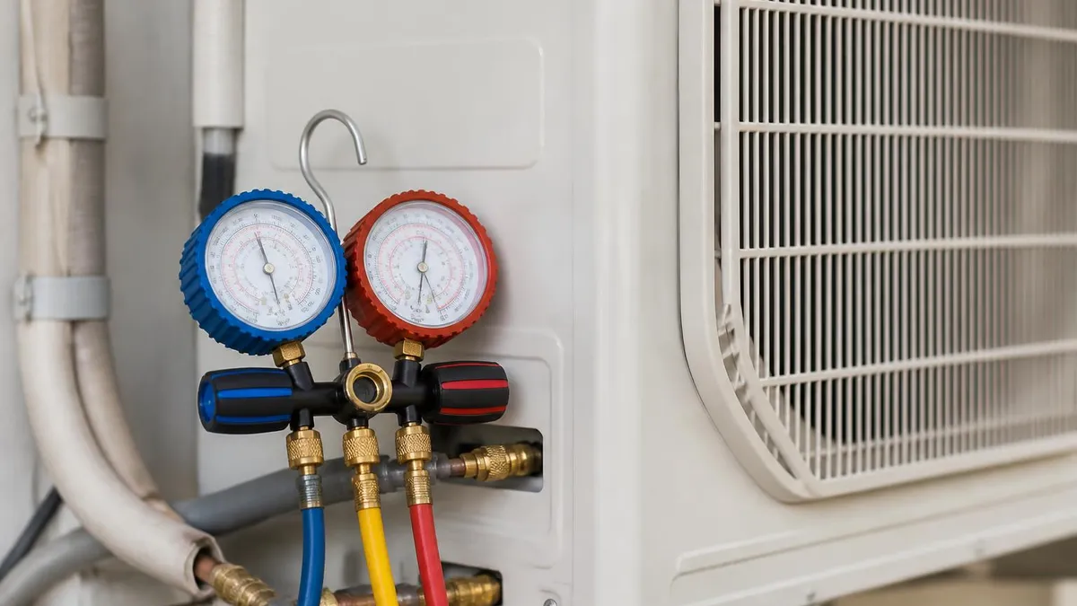
Choosing the Right Multimeter for HVAC Work
Always choose a meter rated CAT III or CAT IV. CAT III covers distribution-level circuits up to 1,000V, while CAT IV covers service entrance equipment. These ratings ensure the meter can safely absorb transient voltage spikes common near electrical panels without arcing or exploding.
True-RMS meters accurately measure non-sinusoidal waveforms produced by variable-frequency drives, ECM motors, and soft-start compressors. Average-responding meters read low on these signals by up to 40%. For modern high-efficiency HVAC equipment, true-RMS is a non-negotiable requirement for accurate diagnostics.
Run and start capacitors are among the most common HVAC failure points. A meter with a microfarad (µF) function lets you test capacitors in place or on the bench without a separate dedicated tester. Look for a range that covers 0.1 µF to at least 2,000 µF to span all HVAC capacitor sizes.
Combination clamp meters that also read temperature via a K-type thermocouple probe are popular among HVAC technicians because they replace two tools. The clamp jaw measures amperage non-invasively, while the thermocouple checks supply air, return air, refrigerant line temperatures, and heat exchanger surface temperatures.
HVAC work often happens in dimly lit mechanical rooms, attic spaces, and equipment closets. A large-digit backlit display is essential. Look for a minimum of 4,000-count resolution — this gives you one decimal place of precision at the top of each range, which matters when reading millivolts on flame sensors.
Measuring voltage is the most frequent multimeter task on any HVAC service call, and it is where most diagnostic sequences begin. Before checking anything else, a technician should verify that the correct supply voltage is reaching the unit. For residential split systems, this means confirming 240 volts (or 208 volts in some multi-family buildings) at the outdoor disconnect, and 120 volts at the furnace or air handler. Low supply voltage — anything more than five percent below nominal — can cause compressors to draw excessive current, overheat, and trip thermal protectors repeatedly without an obvious cause.
To measure AC supply voltage, set the meter dial to VAC (alternating current voltage) and select a range above the expected reading — typically 300V or 600V for line voltage measurements. Insert the black lead into the COM jack and the red lead into the VΩ jack. Touch the black probe to the neutral or ground terminal and the red probe to each hot leg in sequence.
On a 240-volt circuit you should read approximately 120 volts from each hot leg to neutral, and approximately 240 volts between the two hot legs. Readings outside a plus or minus five percent tolerance warrant a call to the utility or a conversation with the electrical contractor before proceeding with HVAC repairs.
The 24-volt control circuit is where most HVAC electrical diagnostics actually happen, and voltage measurement is the fastest way to trace a fault through the low-voltage wiring. The secondary side of the control transformer should read between 24 and 28 volts AC with no load.
When you energize a call for cooling by jumping R to Y at the thermostat subbase, you should see 24 volts appear at the Y terminal of the control board and at the contactor coil terminals outdoors. If voltage stops at a particular point in the circuit, you have isolated the open — a blown fuse, a bad thermostat contact, a failed pressure switch, or a broken wire.
DC voltage measurements are less common in residential HVAC but appear in commercial controls, building automation systems, and some electronic expansion valve drivers. When measuring DC voltage, set the dial to VDC and observe polarity — the red probe goes to the positive terminal. Many modern programmable thermostats and communicating system controls operate on DC logic signals between 0 and 10 volts. An out-of-range signal voltage can explain why a variable-speed air handler is not modulating correctly even when the hardware is mechanically sound.
Gas furnace diagnostics rely heavily on millivolt and low-voltage AC measurements. The hot surface igniter circuit typically operates at 120 volts AC, and you can verify it is being energized by measuring across the igniter terminals with the meter set to 200V AC during a call for heat.
A flame sensor generates a DC microamp signal that requires a specialized microamp adapter or a high-quality DMM with a microamp function — the signal typically runs between 0.5 and 10 microamps, and a reading below 1 microamp usually means the sensor rod needs cleaning or replacement. Some technicians measure millivolts across the flame sensor circuit as a proxy check.
Heat pump systems add reversing valve voltage checks to the diagnostic sequence. On most heat pumps, the reversing valve solenoid is energized in cooling mode (O-terminal energized) or in heating mode (B-terminal energized), depending on the manufacturer. Measuring whether 24 volts AC is present at the reversing valve solenoid while the unit is in each mode tells you immediately whether the control board is commanding the valve correctly, separating a controls problem from a mechanical valve failure. This single voltage check can save a technician from unnecessarily replacing a perfectly functional reversing valve.
Voltage drop testing is a diagnostic technique that goes beyond simply measuring presence or absence of voltage — it measures the quality of a connection or conductor under load. To perform a voltage drop test, apply power to the circuit and measure the voltage across a specific component or segment of wire while current is flowing.
A healthy wire or connection should show less than 0.5 volts of drop. More than one or two volts of drop across a contactor, disconnect blade, or wire connection indicates excessive resistance caused by corrosion, loose terminations, or heat damage, and that connection should be cleaned or replaced before it causes further damage.
HVAC Practice Test Questions
Prepare for the HVAC - Heating Ventilation and Air Conditioning exam with our free practice test modules. Each quiz covers key topics to help you pass on your first try.
HVAC Air Conditioning
HVAC Exam Questions covering Air Conditioning. Master HVAC Test concepts for certification prep.
HVAC Code Compliance
Free HVAC Practice Test featuring Code Compliance. Improve your HVAC Exam score with mock test prep.
HVAC Electrical Controls
HVAC Test Prep for Electrical Controls. Practice HVAC Quiz questions and boost your score.
HVAC Energy Efficiency
HVAC Questions and Answers on Energy Efficiency. Free HVAC practice for exam readiness.
HVAC Heating Systems
HVAC Mock Test covering Heating Systems. Online HVAC Test practice with instant feedback.
HVAC Load Calculations
Free HVAC Quiz on HVAC Load Calculations. HVAC Exam prep questions with detailed explanations.
HVAC Tools and Equipment
HVAC Practice Questions for HVAC Tools and Equipment. Build confidence for your HVAC certification exam.
HVAC Refrigeration
HVAC Test Online for Refrigeration. Free practice with instant results and feedback.
HVAC Safety Practices
HVAC Study Material on Safety Practices. Prepare effectively with real exam-style questions.
HVAC System Design
Free HVAC Test covering System Design. Practice and track your HVAC exam readiness.
HVAC Thermodynamics
HVAC Exam Questions covering Thermodynamics. Master HVAC Test concepts for certification prep.
Resistance, Capacitance, and Continuity Testing in HVAC Systems
Resistance testing with an ohmmeter is performed with all power disconnected and locked out. Set the meter to the ohms (Ω) function and touch the probes together first to verify a near-zero reading, confirming the leads and meter are working correctly. For motor windings, a healthy single-phase motor should show a few ohms to tens of ohms between each winding terminal and an open circuit (OL) between any terminal and ground. A reading of zero ohms to ground indicates a winding shorted to the motor frame, while infinite resistance between winding terminals indicates an open winding — both require motor replacement.
Gas valve coils typically measure between 30 and 100 ohms depending on the manufacturer and valve model. A coil reading significantly outside the specification range — especially zero ohms or infinite ohms — means the coil is shorted or open and needs replacement. Thermostat heat anticipator resistors usually measure 0.2 to 1.5 ohms. Transformer primary windings measure hundreds of ohms and secondary windings measure a few ohms. These reference values let you quickly validate or condemn a component before ordering a replacement part, reducing unnecessary callbacks caused by misdiagnosis.

Digital Multimeter vs. Analog Multimeter for HVAC Work
- +Digital displays eliminate parallax reading errors and are far easier to read in poor lighting conditions
- +Autoranging function selects the correct measurement range automatically, speeding up diagnostics
- +True-RMS digital meters accurately measure distorted waveforms from VFDs and ECM motors
- +Data-hold and min/max capture functions record intermittent readings that disappear before you can write them down
- +Modern digital meters include capacitance, frequency, and temperature functions that analog meters cannot offer
- +Overload protection circuits in digital meters prevent damage from accidental connection to wrong terminals
- −Digital meters can be slower to observe trending readings since the display updates in discrete steps rather than a smooth needle sweep
- −Battery dependency means a dead battery at the wrong moment leaves you without a working instrument
- −High-quality true-RMS CAT III digital meters cost significantly more than basic analog models
- −Some technicians find analog needle meters more intuitive for observing circuit behavior during startup transients
- −Screen glare in bright outdoor sunlight can make digital displays difficult to read on rooftop units
- −Complex menu navigation on high-feature digital meters adds a learning curve compared to a simple analog selector dial
HVAC Multimeter Safety and Best Practice Checklist
- ✓Inspect test leads for damaged insulation, bent probes, or loose connector pins before every use.
- ✓Verify the meter is rated CAT III or CAT IV for the voltage level of the circuit you are testing.
- ✓Confirm the meter is set to the correct function and range before touching any live terminal.
- ✓Insert test leads into the correct jacks — move the red lead to the correct amperage jack when measuring current.
- ✓Lock out and tag out power before performing any resistance or continuity measurement.
- ✓Discharge capacitors through a bleed resistor before measuring capacitance or working near capacitor terminals.
- ✓Keep one hand in your pocket or behind your back when probing live circuits near electrical panels.
- ✓Replace the meter battery when the low-battery indicator appears to maintain measurement accuracy.
- ✓Store test leads coiled loosely without tight kinks that crack lead insulation over time.
- ✓Verify meter accuracy periodically against a known voltage source such as a fully charged 9-volt battery.
Replace Any Capacitor Reading More Than 10% Below Its Rated Value
Even if a motor is still running, a capacitor that measures more than 10% below its labeled microfarad rating is causing the motor to work harder than designed. This accelerates winding insulation breakdown and dramatically shortens motor life. Replacing a $15–$40 capacitor proactively is almost always cheaper than replacing the $200–$800 motor it is killing.
Diagnosing common HVAC faults efficiently comes down to following a logical measurement sequence rather than randomly testing components. When a technician arrives at a no-cooling call, the fastest path to a diagnosis starts with confirming 240 volts at the outdoor disconnect, then measuring whether the contactor is energizing, then checking amperage on each leg of the compressor. This linear approach — power available, control command present, load responding, load drawing correct current — localizes the fault to a specific component within minutes rather than hours of guesswork.
A contactor that is not pulling in despite 24 volts being present at its coil terminals usually means the coil itself has failed. Measure the coil resistance — a healthy coil reads between 10 and 25 ohms on most residential contactors. An open coil reads infinite resistance (OL on the display), while a shorted coil reads near zero ohms and will blow the control fuse.
Either extreme requires contactor replacement. If 24 volts is not arriving at the coil, the fault is upstream — check the high-pressure switch, low-pressure switch, freeze stat, or thermostat wiring depending on which safety controls are in the low-voltage circuit.
Compressor amperage measurements are one of the most informative readings you can take on a cooling system. Using a clamp meter around a single conductor feeding the compressor, compare the measured amperage against the rated load amperage (RLA) stamped on the compressor nameplate. Operating within 10 percent of RLA at normal load conditions indicates a healthy compressor. Amperage significantly above RLA, especially combined with high discharge pressure, points to refrigerant overcharge, condenser airflow restriction, or a mechanically inefficient compressor. Amperage well below RLA can indicate low refrigerant charge or a compressor that is not pumping efficiently.
Blower motor diagnostics follow a similar voltage-then-resistance-then-amperage sequence. Confirm 120 or 240 volts is arriving at the motor terminals during a call for fan operation. Then, with power off, check resistance between each winding lead and the motor frame — values should be infinite (open circuit), indicating no ground fault. Check winding-to-winding resistance and compare it to the motor's wiring diagram.
Finally, restore power and clamp-test the amperage on the common leg, comparing it against the full-load amperage (FLA) on the motor nameplate. An ECM (electronically commutated motor) requires a slightly different approach — its module controls speed, so amperage varies with airflow demand and you need to evaluate it in the context of the commanded speed signal.
Heat exchanger integrity is an area where electrical measurements can provide an indirect diagnostic clue. A cracked heat exchanger sometimes causes carbon monoxide (CO) to enter the supply air stream, but before pulling out a combustion analyzer, a technician who notices that the limit switch trips repeatedly can use the multimeter to check whether the limit is opening at a temperature below its rating — which would point to excessive heat buildup caused by restricted airflow over a cracked and partially blocked heat exchanger.
Measuring supply air temperature with the thermocouple probe while the furnace runs is another way to characterize the heat exchanger's thermal performance.
Condenser fan motor failures are frequently misdiagnosed as refrigerant or compressor problems because a stopped condenser fan causes high head pressure and compressor lockout on the high-pressure switch. Before condemning the compressor or charging the system, always verify that the condenser fan is spinning at the correct speed.
Measure voltage at the fan motor terminals to confirm it is being commanded to run, then check amperage. A fan motor drawing zero amps despite 240 volts at its terminals has an open winding and needs replacement. A motor drawing high amps and turning slowly may have a failed run capacitor, which is easily confirmed with the capacitance test function.
Intermittent faults are the most challenging diagnostics in HVAC work, and this is where the min/max capture function of a good digital multimeter becomes invaluable. By placing the meter in min/max mode across a control circuit and leaving it connected during a service call, you can capture voltage spikes, dropouts, or brief contact failures that occur only when the system is under thermal or vibration load.
When the customer calls back saying the system stopped again, you can review what the meter recorded and often identify the exact moment and magnitude of the fault — turning a frustrating callback into a straightforward repair.
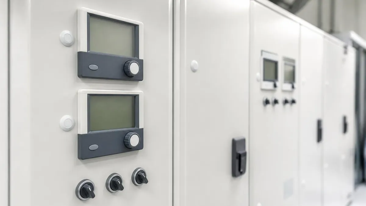
Resistance and continuity functions inject their own internal test current into the circuit. If external voltage is present, you will damage the meter, blow its internal fuse, or receive an electric shock. Always confirm power is locked out and verify with a voltage measurement before switching to the ohms or continuity function. This rule applies even to low-voltage 24-volt control circuits, which can still damage meter electronics.
Preparing for an HVAC certification exam means demonstrating theoretical knowledge of electrical principles as well as practical measurement skills, and the multimeter is central to both. State licensing exams, the NATE (North American Technician Excellence) certification, and EPA Section 608 certification all include questions about Ohm's Law, electrical measurements, and the proper interpretation of meter readings in field scenarios. Understanding how voltage, amperage, resistance, and capacitance relate to each other mathematically is as important as knowing where to place the probes on the equipment.
Ohm's Law — the relationship that voltage equals current multiplied by resistance (V = IR) — governs every electrical measurement in HVAC diagnostics. If you know any two of the three values, you can calculate the third. For example, if a contactor coil is specified to draw 0.3 amps at 24 volts, you can calculate that its resistance should be 24 ÷ 0.3 = 80 ohms.
If your meter reads 40 ohms, something is wrong — either the specification is incorrect, the coil windings are shorted, or the coil is warming up and has not reached operating temperature yet. This kind of cross-checking between measured and calculated values is what separates a systematic diagnostician from someone who only knows how to operate the meter mechanically.
Power calculations matter in HVAC work because oversized or undersized electrical components create reliability problems. Power in watts equals voltage multiplied by amperage (W = V × A) for purely resistive loads like heat strips. For motor loads with power factor, you need to account for the phase angle between voltage and current waveforms — this is precisely why true-RMS meters matter, as they accurately measure the actual power being consumed rather than an approximated value.
When sizing a heat strip for an air handler, verifying that the actual measured amperage multiplied by the measured voltage stays within the nameplate wattage keeps the system within its design parameters and prevents nuisance breaker trips.
Transformer testing is a fundamental skill taught in every HVAC electrical module and frequently appears on certification exams. Measure the primary voltage first — it should match the nominal line voltage within five percent. Then measure the secondary voltage with no load connected — it should read the rated secondary voltage, typically 24 volts.
Finally, measure the secondary voltage with the control circuit connected and energized. A significant voltage drop under load (below 21 volts) indicates either a transformer that is undersized for the connected load, a transformer with weakened core insulation, or a short circuit somewhere in the secondary circuit drawing more current than the transformer is rated for.
The skills for using an HVAC multimeter correctly translate directly into exam success because certification bodies know that electrical competency is a safety-critical skill. Exam questions about meter usage test your ability to select the correct function, predict what a meter should read in a described circuit condition, and identify what an unexpected reading would indicate. Practicing these scenarios with a real meter on training equipment before exam day builds the pattern recognition that lets you answer these questions quickly and confidently rather than having to reason through them from scratch under time pressure.
Field experience and exam preparation reinforce each other in HVAC electrical training. Every service call where you methodically measure voltage before resistance, verify your readings make sense against Ohm's Law, and document your findings builds the mental framework that exam questions are designed to test. Technicians who practice writing down their meter readings and explaining the diagnostic logic behind each step tend to score higher on certification exams because the exams are written to reflect exactly this kind of structured, evidence-based reasoning process rather than trial-and-error component replacement.
Resources like practice exams accelerate exam readiness by exposing you to the specific question formats and technical vocabulary used on certification tests. Working through scenario-based electrical questions — where you are given a described fault condition and a set of meter readings and asked to identify the failed component — mirrors exactly the cognitive process of real-world diagnostics. Combined with hands-on meter practice on real HVAC equipment, targeted exam preparation gives you the fastest path from beginner technician to certified professional.
Building lasting multimeter proficiency in HVAC work requires developing consistent habits around instrument care, calibration awareness, and systematic measurement protocols. A technician who always follows the same sequence of steps — inspect leads, verify function and range, lock out before resistance checks, document readings — makes fewer errors and builds a reliable reputation with customers and employers. These habits are easiest to establish early in a career but can be developed at any stage through deliberate practice and self-review after each service call.
Calibration is a topic that many field technicians overlook, but it matters more than most people realize for accurate HVAC diagnostics. Professional-grade digital multimeters maintain their factory calibration for years under normal use, but a meter that has been dropped, exposed to extreme heat, or used near strong magnetic fields can drift out of specification without any visible indication.
If you are troubleshooting a system where your readings do not make logical sense — for example, voltage appears correct but components behave as if they are starved for power — cross-checking your meter against a second known-good meter is a quick sanity check that can save hours of chasing a phantom fault.
Meter accessories expand diagnostic capability significantly beyond what the basic instrument provides. A flexible-jaw clamp attachment allows amperage measurements in tight wiring compartments where a standard clamp meter jaw will not fit. K-type thermocouple probes enable simultaneous temperature and electrical measurements without carrying a separate thermometer. Current clamp adapters that output a millivolt signal allow basic voltage-only meters to perform amperage measurements in a pinch. Magnetic hanging straps free both hands for probing while the meter hangs in view. These low-cost accessories — most under thirty dollars — make a good meter even more versatile on a complex service call.
Documentation practices tied to multimeter readings are increasingly important in commercial HVAC service, where written records support warranty claims, service agreements, and equipment replacement recommendations. Many experienced technicians photograph their meter display when they find a critical reading — a low supply voltage, a failing capacitor reading, an overamping compressor — to support their diagnosis report to the building owner or facilities manager. This practice also protects the technician professionally by creating an evidence trail that shows the diagnostic process that led to a repair recommendation, which matters if a repair decision is later questioned.
Training new technicians on multimeter use is a responsibility that experienced HVAC professionals take seriously because electrical safety mistakes have serious consequences. When mentoring an apprentice, the most important habits to instill are always checking the meter function before probing, always locking out before switching to resistance functions, and always thinking about what the meter should read before touching the probes to the circuit.
Pre-prediction — forming an expectation before measuring — catches wiring errors, unexpected circuit states, and meter setup mistakes before they cause damage or injury. It is also the single most effective way to accelerate diagnostic intuition, because a reading that differs from your prediction triggers the right question: why?
The HVAC industry is evolving rapidly toward communicating systems, smart controls, and building automation integration that requires technicians to understand digital communication signals alongside traditional analog electrical measurements. Modern communicating HVAC systems from manufacturers like Carrier, Lennox, and Trane use proprietary serial communication buses that carry equipment status, fault codes, and operating parameters digitally.
A standard multimeter cannot decode these signals, but it can verify that the physical communication wires have continuity, are not shorted together, and are not carrying voltage that would damage the communication modules. Understanding the boundary between what a multimeter can test and where a manufacturer's diagnostic tool takes over is an important part of professional-level HVAC electrical competency.
Investing in quality multimeter education pays dividends throughout an entire HVAC career. The fundamentals of voltage measurement, Ohm's Law application, capacitor testing, and motor winding analysis do not change as equipment evolves — the same principles that apply to a 1970s window air conditioner apply equally to a 2026 inverter-driven variable-refrigerant-flow system.
Building a deep, flexible understanding of electrical measurement early in your career gives you the diagnostic foundation to adapt to new technologies confidently, pass certification exams at every level, and provide the kind of fast, accurate, and transparent service that builds a loyal customer base and a long-term professional reputation.
HVAC Questions and Answers
HVAC Sales: The Complete Guide to Selling Heating and Cooling Systems, Building Customer Trust, and Closing More Deals

HVAC Air Duct Sealing: The Complete Homeowner and Contractor Guide to Sealing Ductwork for Efficiency, Comfort, and Indoor Air Quality
HVAC Solutions: The Complete Guide to Heating, Cooling, and Indoor Air Quality Systems for Homes and Buildings

Commercial HVAC Repair: Systems, Costs, and Service Strategies
HVAC Apprenticeship Programs: Your Complete Guide to Starting a Hands-On Career in Heating, Ventilation, and Air Conditioning
About the Author

NATE Certified HVAC Technician & Licensing Exam Trainer
Universal Technical InstituteMike Johnson is a NATE-certified HVAC technician and EPA 608 universal-certified refrigerant handler with a Bachelor of Science in HVAC/R Technology. He has 19 years of commercial and residential HVAC installation and service experience and specializes in preparing technicians for NATE certification, EPA 608, A2L refrigerant safety, and state HVAC contractor licensing examinations.