HVAC Wiring: A Complete Guide to Thermostat, Control Board, and Low-Voltage Wiring
Master hvac wiring basics — thermostat wires, color codes, control boards, and low-voltage circuits. ✅ Learn what each wire does and when to call a pro.
Understanding hvac wiring is one of the most practical skills a homeowner or aspiring HVAC technician can develop. Whether you are trying to replace a thermostat, troubleshoot a system that won't turn on, or prepare for a licensing exam, knowing how wires connect and what each color means can save you hours of frustration and hundreds of dollars in unnecessary service calls. HVAC wiring spans two distinct voltage levels — low-voltage control circuits typically running at 24 volts AC and line-voltage power circuits running at 120 or 240 volts — and each has its own rules, tools, and safety requirements.
The low-voltage side of an HVAC system is where most homeowners interact with wiring. The thermostat connects to the air handler or furnace through a multi-conductor cable, commonly called thermostat wire or 18-gauge wire, that carries signals telling the system when to heat, cool, run the fan, or switch to emergency heat. Each conductor in the cable is color-coded, and while industry conventions exist, variations between manufacturers mean you should never assume a wire's function from its color alone — always verify with a wiring diagram or multimeter before making connections.
Line-voltage wiring, by contrast, powers the compressor, air handler blower motor, condenser fan, and electric heating elements. This wiring operates at potentially lethal voltages and must comply with the National Electrical Code (NEC) as well as local amendments. Only licensed electricians or HVAC technicians with proper training should work on line-voltage components. Mistakes at this level can cause fires, equipment damage, or fatal electrical shocks, so understanding where your competence ends is just as important as knowing how to wire a thermostat correctly.
One of the most common sources of confusion in residential HVAC wiring is the difference between a two-stage system and a single-stage system. Single-stage equipment uses fewer thermostat terminals and simpler wiring, while two-stage and variable-speed systems may require additional conductors for staging signals, humidity control, or communication protocols such as Daikin's proprietary wiring or the newer S-Bus standard. When upgrading a thermostat or adding a smart thermostat, verifying compatibility before purchase will prevent a frustrating installation experience where the new device simply will not function with your existing equipment.
Heat pumps add another layer of complexity to HVAC wiring because they perform both heating and cooling functions. A heat pump thermostat requires an O or B wire to control the reversing valve, an E or AUX terminal for emergency and auxiliary heat, and sometimes a separate wire for the indoor air handler's electric heat strip staging. Understanding the difference between an O-wire system (where the valve energizes in cooling mode) and a B-wire system (where it energizes in heating mode) is critical to correct wiring and preventing the system from running in the wrong mode.
Control board wiring is the next step beyond thermostat connections. The furnace or air handler control board acts as the brain of the system, receiving low-voltage signals from the thermostat and then energizing the appropriate relays and contactors to start motors, open gas valves, and sequence operations safely. A failed control board is a common HVAC repair, and knowing how to read the board's wiring diagram, identify blown fuses, and trace signal paths with a multimeter can help you diagnose whether the board itself has failed or whether a faulty downstream component is the root cause of the problem.
This guide walks through every major aspect of HVAC wiring, from thermostat wire color codes and terminal labels to control board diagnostics, heat pump wiring, and safety best practices. Whether you are a homeowner building confidence before calling a technician, a student preparing for the EPA 608 or state HVAC licensing exam, or a working technician brushing up on best practices, the sections below provide the structured, accurate information you need to work safely and effectively with HVAC electrical systems.
HVAC Wiring by the Numbers
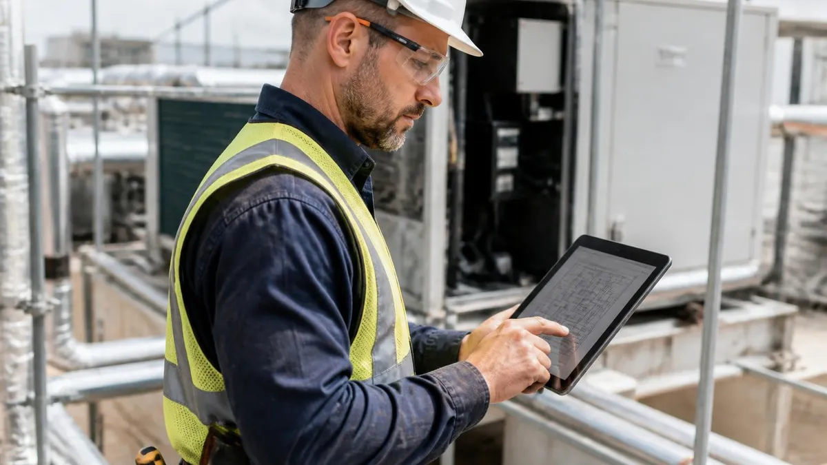
How to Read and Follow an HVAC Wiring Diagram
Locate the Wiring Diagram
Identify Voltage Levels
Trace the Control Circuit
Match Wire Colors to Terminals
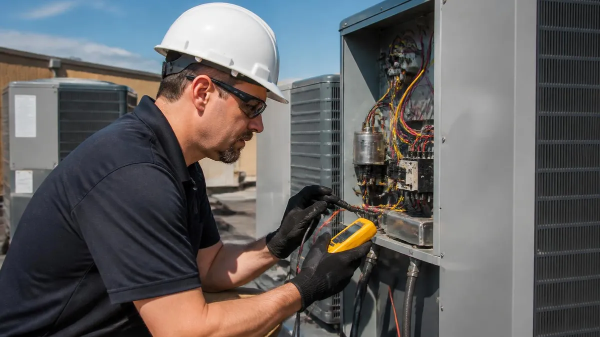
Verify with a Multimeter
Power Up and Test Each Mode
The HVAC control board is the central hub of low-voltage wiring in a forced-air system, and understanding how it is wired is essential for both diagnostics and installation. The board typically receives 120V or 240V line power from the main electrical panel through a dedicated circuit, then steps it down through an onboard transformer to produce the 24V AC that powers the control circuit.
This transformer has a primary winding connected to line voltage and a secondary winding that outputs 24V across the R and C terminals. If the transformer fails — often from a short circuit in the thermostat wiring — the entire control circuit loses power and the system will not respond to any thermostat commands.
Terminal labeling on control boards follows conventions established decades ago but can vary between manufacturers. The R terminal (Red wire conventionally) is the 24V hot leg from the transformer. In systems with separate heating and cooling transformers, this terminal may be split into RH (red-heat) and RC (red-cool), with a jumper wire shorting them together when a single transformer serves both functions.
Removing this jumper is required when installing a thermostat with its own power source or when the system has two separate 24V transformers. Forgetting to remove the jumper when it should be removed can blow the transformer or damage the new thermostat.
The C terminal (Common wire, often blue or black) completes the 24V circuit back to the transformer secondary. Many older homes were wired without a dedicated C wire because early thermostats did not require a continuous power source — they used the heating or cooling circuit itself to steal a small trickle of power for their electronics.
Modern smart thermostats universally require a true C wire for reliable operation. When a C wire is absent, installers have several options: run a new thermostat cable, use a C-wire adapter kit that repurposes an unused conductor, or install a 24V add-a-wire adapter that shares the existing wiring.
The Y terminal controls the cooling contactor in the outdoor condensing unit. When the thermostat calls for cooling, it completes the 24V circuit between R and Y, which energizes the Y relay on the control board. This relay in turn closes a set of contacts that sends 24V out to the contactor coil in the outdoor unit, pulling in the contactor and energizing the compressor and condenser fan motors.
A Y1 and Y2 terminal configuration indicates a two-stage compressor where Y1 activates first-stage (lower capacity) cooling and Y2 activates full capacity, allowing the system to run more efficiently during mild weather conditions.
The W terminal controls heating. In a gas furnace, energizing W initiates the heating sequence: the inducer motor starts, a pressure switch verifies draft, the igniter glows or sparks, the gas valve opens, the burner ignites, the heat exchanger warms up, and finally the supply air blower starts at a delay determined by the fan control.
Each of these steps involves the control board monitoring safety switches in series. If any switch opens — an overheating limit switch, a clogged-drain float switch, or a failed pressure switch — the W circuit breaks and the board shuts down the heating sequence, often logging a fault code to assist diagnostics.
The G terminal controls the indoor blower fan independently of heating or cooling calls. When the thermostat fan switch is set to ON rather than AUTO, G is continuously energized, running the blower to circulate air without conditioning it.
In modern variable-speed air handlers, the G signal tells the motor control board to run at a low continuous airflow speed, which helps maintain consistent air circulation, reduce humidity by running the evaporator coil longer, and improve indoor air quality when a media filter or UV system is installed. The O and B terminals are specific to heat pump systems and are covered in detail in the tabs section below.
Understanding control board wiring also means knowing how to identify common failure points. Blown low-voltage fuses — typically 3-amp or 5-amp mini-blade fuses mounted directly on the control board — are the most frequent cause of a completely unresponsive HVAC system. These fuses protect the transformer and control circuit from short circuits.
If a fuse blows repeatedly after replacement, a short circuit exists somewhere in the thermostat wiring, often caused by a wire pinched in the cabinet door, a staple driven through a conductor in the wall, or a faulty zone valve or damper actuator shorting to ground. Finding and eliminating the short before replacing the fuse again is essential to prevent transformer damage.
HVAC Wiring by System Type
A split system with a gas furnace and central air conditioner represents the most common residential HVAC wiring configuration in the United States. The thermostat cable typically requires five conductors minimum: R (24V power), C (common), Y (cooling call), G (fan call), and W (heat call). The furnace control board receives all five signals, energizes its own blower and gas valve for heat, and passes the Y signal to the outdoor condensing unit through a separate two-conductor wire running from the air handler to the condenser disconnect box.
When upgrading to a two-stage system, a sixth conductor (Y2 or W2) becomes necessary for the second-stage signal. Many installers run an 8-conductor thermostat cable during new construction or major retrofits to allow for future upgrades without rewiring the entire system. The outdoor condensing unit itself requires only two low-voltage conductors from the air handler — typically Y and C — to energize the contactor coil, though some communicating systems use a proprietary two-wire communication bus instead of conventional terminal wiring.
DIY HVAC Thermostat Wiring vs. Hiring a Professional
- +Saves $75–$150 in typical thermostat installation labor costs
- +Builds practical knowledge useful for future troubleshooting
- +Thermostat replacement carries low shock risk at 24V low voltage
- +Manufacturer wiring guides and YouTube tutorials are widely available
- +Smartphone-based multimeter apps make voltage verification easy
- +Replacing like-for-like thermostats is straightforward with labeled wires
- −Incorrect wiring can blow the transformer or damage the control board
- −Heat pump O/B configuration errors cause system to heat and cool in reverse
- −Missing C wire requires additional adapter purchase or new cable run
- −Communicating system thermostats require professional programming tools
- −Errors on line-voltage components (240V condensers) create electrocution risk
- −Some local codes require licensed technicians for any HVAC electrical work
HVAC Wiring Safety and Pre-Work Checklist
- ✓Turn off the system at the thermostat and shut off the disconnect switch before opening any electrical panel.
- ✓Verify power is off with a non-contact voltage tester before touching any wires.
- ✓Photograph all existing wiring connections before disconnecting anything.
- ✓Label each wire with masking tape and a marker to match its terminal before removal.
- ✓Inspect thermostat cable insulation for pinched, burned, or cracked sections along its entire run.
- ✓Check the low-voltage fuse on the control board and replace if blown before diagnosing further.
- ✓Verify R-to-C voltage reads 24–28V AC on a multimeter before assuming the transformer is good.
- ✓Confirm the heat pump thermostat's O/B setting matches the equipment brand's reversing valve convention.
- ✓Test each operating mode (heat, cool, fan) individually after completing wiring before closing panels.
- ✓Secure all wire connections firmly — loose spade terminals on control boards are a leading cause of intermittent faults.
One photo saves hours of troubleshooting
Before removing a single wire from a thermostat or control board, take a clear, well-lit photo of every terminal. If you're replacing a thermostat with a different brand, the terminal labels may not match one-to-one, but having a photo of the original wiring means you can always trace back to a known-good configuration. This single habit prevents the most common DIY wiring mistake — forgetting which wire went where — and is standard practice among professional HVAC technicians during any wiring change.
Common HVAC wiring problems fall into a handful of repeating patterns that experienced technicians learn to recognize quickly. A system that powers on at the thermostat but produces no heating or cooling response often has a blown 3-amp or 5-amp control board fuse as its root cause.
This fuse blows when the 24V circuit is shorted — either from a wire touching bare metal in the cabinet, a pinched thermostat cable, or a failed zone valve or motorized damper that has developed an internal short. Always check for and eliminate the short before replacing the fuse, since a replacement fuse will blow immediately if the short persists.
A system that cools but does not heat, or heats but does not cool, typically has a broken conductor in the thermostat cable rather than a component failure. This is especially common after renovations, when a staple gun may have penetrated a wire buried in drywall.
Trace the thermostat cable from the thermostat to the air handler, checking for any penetrations, tight bends, or areas where the cable passes through studs or plates. Using a multimeter in continuity mode, test each conductor individually from one end to the other with the system powered off to find the broken conductor. If the cable cannot be repaired, running a new cable is the definitive fix.
An intermittent problem — a system that works sometimes but not others — is one of the most challenging wiring issues to diagnose. Intermittent faults are often caused by loose spade terminal connections on the control board, corrosion on terminal pins, or a thermostat baseplate that is slightly warped and not making consistent contact with the wiring terminals.
Vibration from the blower motor can also cause loose connections to open and close, producing faults that disappear when you're standing in front of the equipment. The diagnostic approach is to reseat every connector, apply a small amount of dielectric grease to low-voltage terminals prone to corrosion, and conduct an extended test run while monitoring the system.
A furnace that short-cycles — starting, running briefly, then shutting off before satisfying the thermostat — often involves an open limit switch. The high-temperature limit switch is wired in series with the control circuit and opens when the heat exchanger overheats, cutting power to the gas valve. After the unit cools, the limit switch resets and the cycle repeats.
This wiring-adjacent problem is not a wiring failure per se, but it manifests as an interrupted control circuit. Root causes include a dirty air filter restricting airflow, a closed supply register in a zone, or a failed blower capacitor preventing the fan from running at full speed, all of which reduce heat dissipation across the exchanger.
Wiring problems in outdoor condensing units often present as a system where the air handler blower runs but the compressor and condenser fan do not operate. The most common cause is a failed contactor — the heavy-duty relay that connects line voltage to the compressor and fan motors. The contactor coil is part of the 24V control circuit, energized by the Y terminal signal from the thermostat.
Testing the contactor involves measuring 24V across the coil terminals while a cooling call is active, then measuring line voltage across the load-side contacts. If 24V is present at the coil but the contacts do not close, the contactor needs replacement — a straightforward repair for a qualified technician.
Wiring in multi-speed and variable-speed air handlers has become more complex in recent years, particularly with the widespread adoption of ECM (Electronically Commutated Motor) blower motors. These motors are controlled by a motor control module that interprets voltage signals from the furnace control board to set blower speed. The tap wiring on an ECM air handler — typically 0–10V analog signals or discrete 24V tap signals — determines airflow for heating, cooling, and continuous fan modes.
Incorrect tap configuration results in too much or too little airflow, causing poor system efficiency, comfort complaints, and potentially coil icing in the case of insufficient cooling airflow. Always consult the air handler's wiring diagram and the equipment's static pressure specifications when setting ECM tap configurations.
Finally, condensate drain float switches are a frequently overlooked wiring component that causes many unexplained system shutdowns. These switches are wired in series with the low-voltage control circuit — typically in series with the Y cooling signal or the R hot leg — and open when the condensate drain pan fills with water.
When the switch opens, the system shuts down to prevent water overflow damage. Homeowners and technicians who are unaware of this switch often spend considerable time diagnosing control boards and thermostats before discovering a simply clogged condensate drain line is the root cause. Clearing the drain and resetting the float switch immediately restores normal operation in these cases.
The 240V circuits powering your air conditioner condenser and electric heat strips can deliver fatal shocks. Before opening any outdoor unit, disconnect the power at the outdoor disconnect box and verify with a non-contact voltage tester that voltage is absent. Capacitors inside the condensing unit store a lethal charge even after the disconnect is pulled — always discharge capacitors through a 20,000-ohm resistor before touching terminals. If you are not trained in electrical safety procedures, this work requires a licensed HVAC technician or electrician.
For students and working technicians preparing for HVAC licensing or certification exams, HVAC wiring is one of the most heavily tested subject areas. State licensing boards and certification bodies recognize that electrical competence is directly tied to public safety — a miswired furnace can cause a gas explosion, and an incorrectly wired heat pump can run in the wrong mode indefinitely, increasing energy bills and shortening equipment life. Exam questions on wiring typically test your ability to read ladder diagrams and wiring schematics, identify the function of specific terminals and components, and trace fault conditions through a described circuit.
Ladder diagrams are the standard format used in HVAC training manuals and manufacturer service literature. In a ladder diagram, the two vertical rails represent the power supply — typically L1 (hot) and L2 or N (neutral) for line-voltage circuits, or R and C for low-voltage circuits.
The horizontal rungs between the rails represent individual control circuit paths, with loads (relay coils, solenoids, motors) and switches (thermostats, limit switches, pressure switches, contactors) arranged in series and parallel combinations. Reading a ladder diagram from top to bottom traces the operational sequence of the system, which mirrors the actual startup sequence of the equipment.
A common exam scenario presents a ladder diagram with a described fault condition — for example, the compressor runs but the condenser fan does not — and asks you to identify which component has failed. In this case, tracing the condenser fan motor circuit on the ladder diagram reveals that it runs through the contactor (shared with the compressor) plus a separate thermal overload or fan relay.
Since the compressor operates, the contactor is confirmed closed. The fault must therefore be in the fan motor's overload, its run capacitor, or the motor itself. This kind of logical circuit tracing is exactly the reasoning tested on state exams and NATE certification assessments.
Understanding transformer sizing and circuit protection is another key exam topic. The 24V transformer in most residential systems is rated at 40VA (volt-amperes), meaning it can supply a maximum of approximately 1.67 amps at 24V before its thermal overload trips. Adding too many zone valves, damper actuators, or other 24V loads to a single transformer can overload it, causing nuisance trips or premature transformer failure. Exam questions may present a scenario with multiple 24V loads and ask whether the existing transformer is adequately sized, requiring candidates to calculate total VA demand and compare it to transformer rating.
Wire sizing for line-voltage HVAC circuits follows NEC Table 310.16 for conductors in conduit and considers both ampacity and voltage drop. The minimum circuit ampacity (MCA) and maximum overcurrent protection (MOP) values printed on every piece of HVAC equipment's nameplate are the starting point for sizing the circuit breaker and conductors.
The MCA accounts for motor locked-rotor current and specifies the minimum wire size, while the MOP specifies the maximum breaker or fuse size. Running a circuit to an air conditioner without consulting the equipment nameplate — or oversizing a breaker to avoid nuisance tripping — are code violations that can allow dangerous overcurrent conditions to persist without protective interruption.
The relationship between wiring and system efficiency is increasingly tested on modern HVAC exams as the industry shifts toward high-efficiency and variable-capacity equipment. Communicating thermostats and smart controls allow equipment to report real-time performance data, adjust operating parameters dynamically, and perform self-diagnostics. Understanding how these systems communicate — whether through conventional 24V terminal signals, proprietary two-wire buses, or open-standard protocols like BACnet or Modbus in commercial applications — is becoming a baseline expectation for technicians entering the field. NATE, the premier HVAC certification body, has updated its exam content outlines to include communicating controls as a tested competency area.
For anyone serious about advancing their HVAC career, the path from wiring basics to advanced controls knowledge is well-structured through accredited programs, manufacturer training, and exam preparation resources. PracticeTestGeeks offers focused practice quizzes covering HVAC electrical controls, code compliance, and system-specific topics that mirror the difficulty and format of real licensing exams. Using practice tests to identify gaps in your wiring knowledge — especially in the areas of schematic reading, transformer sizing, and heat pump terminal configurations — gives you a targeted study roadmap that is far more efficient than reading textbooks cover to cover without testing retention.
Practical success with HVAC wiring begins with assembling the right tools and developing systematic habits before touching any wires. A quality digital multimeter is the single most important tool, capable of measuring AC and DC voltage, resistance, continuity, and capacitance in a single instrument. For low-voltage work, a multimeter in the $40–$100 range provides all the accuracy needed.
For line-voltage work, choose a meter rated CAT III at minimum, indicating it is designed to withstand the transient voltages present in distribution panels and equipment disconnects. Using an under-rated meter on high-voltage circuits creates a genuine risk of arc flash and instrument destruction.
A non-contact voltage tester (NCV tester) is a complementary safety tool that detects the presence of alternating current through the insulation of a wire without requiring contact with bare conductors. Use this tool to verify that power is absent before opening any electrical enclosure. Develop the habit of testing every wire before touching it — not just the ones you expect to be energized.
Stray voltages from induced fields, backfed circuits, and miswired systems create unexpected hazards for anyone who assumes rather than verifies. The two-second habit of testing with an NCV tester before every connection is what separates experienced technicians from those who end up with shock injuries.
Thermostat wire strippers and small-blade screwdrivers round out the basic HVAC wiring toolkit. Quality wire strippers sized for 18–24 AWG wire strip insulation cleanly without nicking conductors, which can weaken the wire and create failure points at high-flex locations near terminals. A small magnetic-tip screwdriver is invaluable for working inside cramped control boards where a dropped screw is nearly impossible to retrieve. Some technicians carry a telescoping magnet for exactly this purpose. Needlenose pliers and small wire crimpers complete the basic toolkit for control wiring work.
When running new thermostat wire, choosing the right cable type saves future headaches. Standard 18/5 cable (18-gauge, 5 conductors) suits most single-stage gas furnace and air conditioner installations. For heat pumps, 18/8 provides the additional conductors needed for O/B, AUX, and E terminals without immediately exhausting spare conductors. For zoned systems or anticipated smart thermostat upgrades, 18/8 or 18/10 cable provides extra conductors for accessories like humidistats, dehumidistats, ventilation controls, or occupancy sensors. Pulling cable with extra conductors costs almost nothing incremental compared to the cable itself, while rewiring a completed installation is expensive and disruptive.
Labeling wire at both ends during installation is a professional practice that pays dividends for every subsequent service visit. A simple approach is to write the terminal label on a small piece of masking tape wrapped around each conductor at the point where it terminates, on both the thermostat and control board ends of the cable.
More elaborate installations use pre-printed wire markers or heat-shrink labels. The goal is that any technician arriving years later can identify every wire's function without tracing it end to end — a courtesy that dramatically reduces diagnostic time and prevents rewiring errors during equipment replacements.
Understanding manufacturer-specific wiring conventions matters when working on branded systems. Carrier, Trane, Lennox, Rheem, Goodman, and other major manufacturers all publish comprehensive installation and service manuals with wiring diagrams specific to each model. Accessing these documents through manufacturer websites or the equipment nameplate's QR code is always the right starting point for an unfamiliar system. Generic thermostat compatibility charts and third-party wiring guides can be helpful for standard configurations, but when a system has unusual terminal labels or proprietary features, the manufacturer's documentation is definitive.
Finally, know when the job exceeds your qualifications and when a licensed professional is the right choice. Low-voltage thermostat wiring at 24V is genuinely accessible to knowledgeable homeowners who approach the task methodically. Line-voltage wiring, condenser installation, electrical panel work, and any task requiring permits or inspections requires a licensed HVAC technician or electrician in virtually every U.S. jurisdiction.
Investing in professional installation for line-voltage work protects your home, your equipment warranty, your insurance coverage, and most importantly your safety. The money saved by incorrect DIY work on high-voltage systems is never worth the risk, and reputable HVAC professionals are well worth the investment for anything beyond basic control wiring.
HVAC Questions and Answers
Finance a New HVAC System: 2026 Loans, 0% APR, and Rebates
HVAC Duct Repair: Common Issues, Costs, and DIY vs Professional
HVAC School -- Programs, Costs, and Career Paths in 2026
HVAC Advertising: The Complete Playbook for Generating Leads, Booking Calls, and Growing Your Heating and Cooling Business
EPA Certification for HVAC: The Complete Guide to Section 608 Requirements, Exam Prep, and Career Impact
About the Author

NATE Certified HVAC Technician & Licensing Exam Trainer
Universal Technical InstituteMike Johnson is a NATE-certified HVAC technician and EPA 608 universal-certified refrigerant handler with a Bachelor of Science in HVAC/R Technology. He has 19 years of commercial and residential HVAC installation and service experience and specializes in preparing technicians for NATE certification, EPA 608, A2L refrigerant safety, and state HVAC contractor licensing examinations.