
What Does an MRI Machine Look Like? A Complete Visual Guide to MRI Equipment
Discover what an MRI machine looks like inside and out — 📝 components, types, sizes, and how each part functions during a scan.
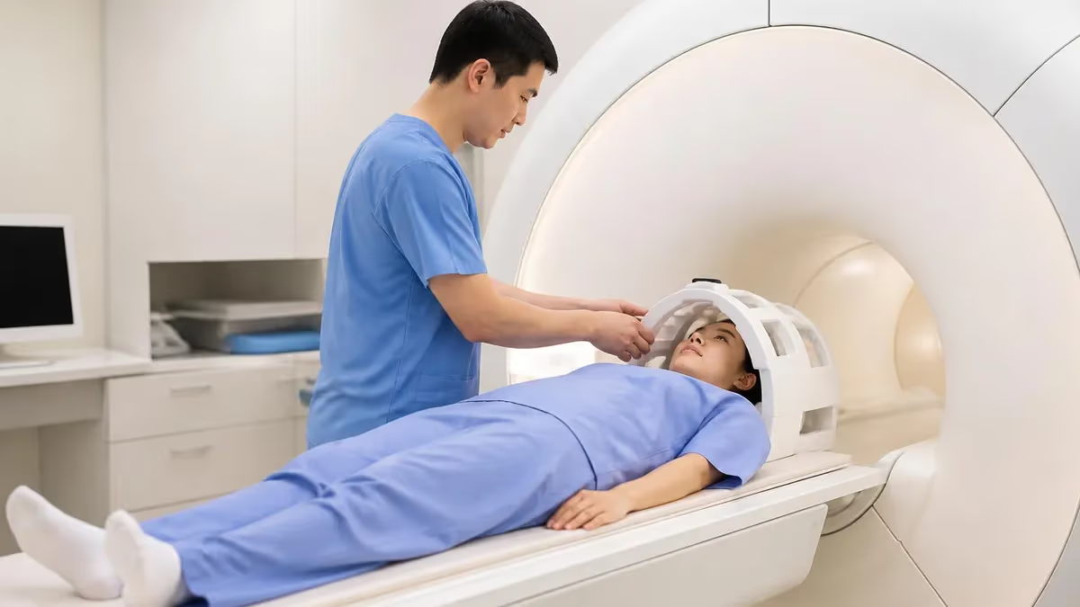
If you have ever wondered what does an MRI machine look like before walking into a radiology suite, you are not alone. The magnetic resonance imaging scanner is one of the most recognizable pieces of medical equipment in the world, yet many patients and students find themselves surprised by its actual size, shape, and complexity when they first encounter it in person.
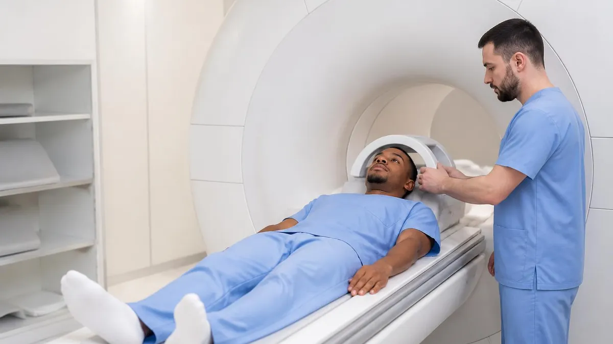
The standard closed-bore MRI scanner resembles a large, white or off-white donut — a thick, cylindrical housing with a central circular tunnel called the bore — and it sits on a motorized patient table that slides smoothly in and out of the machine during each imaging sequence.
The external shell of most clinical MRI systems measures roughly 5 to 7 feet tall, 7 to 8 feet wide, and 6 to 8 feet deep, giving the entire unit a footprint comparable to a compact car. The bore diameter — the opening patients slide into — typically ranges from 60 centimeters in older systems to 70 or even 80 centimeters in modern wide-bore designs built to accommodate larger patients and reduce claustrophobia.
Despite its imposing exterior, the visible housing is essentially a decorative and protective shell that conceals an extraordinarily intricate system of superconducting magnets, radiofrequency coils, gradient coil assemblies, and cryogenic cooling components operating at temperatures near absolute zero.
Inside the bore, patients encounter a smooth, well-lit interior with small ventilation fans that circulate air and reduce the feeling of confinement. Many modern systems also incorporate fiber-optic lighting, ambient sound systems, and even projected images on the interior ceiling to help anxious patients remain calm throughout a scan that may last anywhere from 20 minutes to over an hour. The patient table, known as the examination couch or cradle, is padded and equipped with integrated coil attachments so that surface coils — specialized antennas that improve signal quality — can be positioned precisely over the anatomy being examined.
Understanding the visual anatomy of an MRI scanner matters whether you are a patient preparing for your first scan, a radiologic technology student studying for boards, or a healthcare worker who guides patients through the imaging process. For those exploring the imaging career pathway, our guide on what does an MRI machine look like in the context of specific clinical protocols gives additional perspective on how scanner design influences diagnostic capability for different body regions and pathologies.
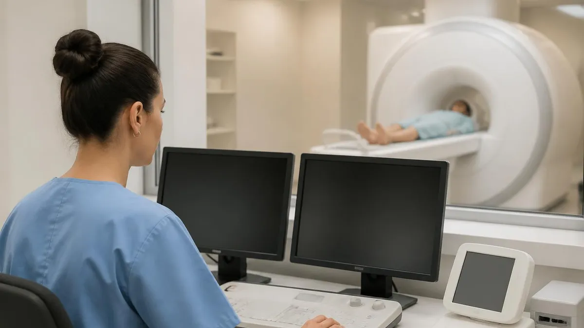
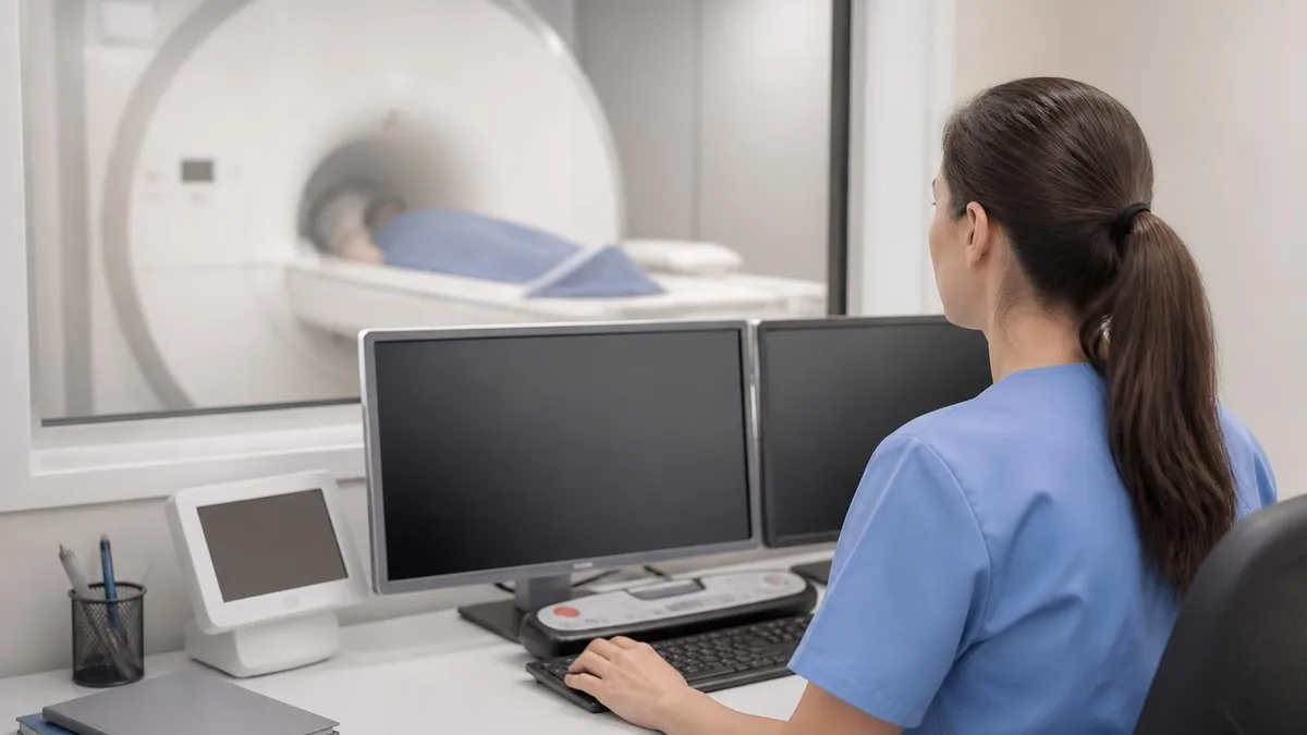
Beyond the main magnet housing, a complete MRI installation includes a separate equipment room packed with computer racks, radiofrequency amplifiers, gradient amplifiers, and the helium compressor system that keeps the superconducting magnet coils at approximately 4 Kelvin — colder than outer space. A control room sits adjacent to the scanning suite behind RF-shielded glass, where the MRI technologist operates the scanner console, monitors patient safety, and reviews images in real time. Together these three interconnected spaces form the complete operational environment of a clinical MRI system.
The color palette of modern MRI machines has shifted significantly over the past two decades. Early systems were almost universally utilitarian white or beige, but manufacturers now offer custom color panels, wood-grain accents, and even pediatric-themed shells with cartoon characters painted on the exterior and bore ceiling. Siemens, GE Healthcare, Philips, Canon Medical, and Hitachi each bring a distinct design language to their flagship systems, so the visual experience can vary considerably from one hospital or imaging center to another, even when the underlying magnetic field strength and clinical capability are comparable.
Field strength — measured in Tesla — also influences the physical appearance of the machine. A 1.5T system and a 3T system may look nearly identical from the outside, but the 3T magnet requires a larger, heavier cryostat and produces a stronger fringe field, often necessitating a bigger room with more extensive radiofrequency shielding. Open MRI systems, which use a C-shaped or two-pillar magnet design instead of the classic tunnel, present an entirely different visual profile and are covered in detail later in this guide.
MRI Machine by the Numbers

Key Physical Components of an MRI Machine
The largest and heaviest component, the superconducting main magnet generates the static magnetic field. It is housed inside a cryostat filled with liquid helium and is the dominant visual element of the scanner's cylindrical exterior shell.
Three sets of gradient coils (X, Y, Z) are embedded inside the bore. They produce the rapid switching magnetic fields that localize signals during imaging and are responsible for the loud banging and knocking sounds patients hear during a scan.
RF coils act as both transmitters and receivers of radiofrequency energy. The body coil is built into the bore wall; surface coils are placed directly on or around the patient's anatomy to maximize signal-to-noise ratio for specific body parts.
The motorized, padded table slides the patient smoothly into the bore. Modern tables float isocenter positioning, allowing precise alignment of the target anatomy with the magnetic field center for optimal image quality.
Behind RF-shielded glass, the technologist console controls all scan parameters. An adjacent equipment room houses gradient amplifiers, RF amplifiers, computer servers, and the helium compressor that maintains cryogenic temperatures.
When radiologic technology students and practicing MRI technologists discuss the different types of MRI scanners, they are usually referring to three broad design categories: closed-bore (tunnel) systems, open MRI systems, and specialized dedicated-extremity scanners. Each category has a strikingly different visual profile, and understanding those differences helps patients set realistic expectations and helps clinicians match equipment to patient population needs. Closed-bore systems are by far the most common and represent the classic donut-shaped machine that most people picture when they think about MRI.
Standard closed-bore systems — whether 1.5T or 3T — feature a cylindrical magnet housing that creates the tunnel patients slide into. The bore depth on most clinical systems runs between 140 and 160 centimeters, meaning a patient whose head is being scanned may have their feet outside the machine entirely, while a patient undergoing an abdominal or cardiac scan will have their torso centered in the bore with both head and feet extending slightly beyond the magnet's opening.
This is a crucial piece of visual information that many patients do not anticipate: even in a closed-bore scanner, the majority of the body scan does not require the patient's entire body to be enclosed in the tunnel simultaneously.
Wide-bore MRI systems represent an evolution of the closed-bore design driven directly by patient experience feedback. Traditional bore diameters were 60 centimeters; wide-bore systems expanded this to 70 centimeters, and some premium systems now offer 80-centimeter openings. Visually, wide-bore machines appear slightly larger in diameter and often have shorter bore depth — as little as 125 centimeters on some models — creating a significantly less confined appearance and experience. These machines have become the standard of care in facilities serving a diverse patient population and are particularly valued in pediatric, bariatric, and oncology settings where patient compliance is critical.
Open MRI systems present a dramatically different visual profile. Instead of a cylindrical tunnel, open MRI uses either a C-arm design — where two large magnetic discs face each other with a gap the patient sits or lies between — or a two-pillar horizontal design.
These machines sacrifice field strength, operating typically between 0.3T and 1.0T compared to the 1.5T–3T of closed systems, but they eliminate claustrophobia almost entirely and allow positioning of patients in weight-bearing upright postures that can reveal pathology invisible on supine closed-bore imaging. They are considerably quieter than closed systems because the gradient coils are less constrained.
Dedicated extremity MRI scanners — sometimes called extremity coil systems or peripheral MRI units — occupy the smallest visual footprint of any clinical MRI system. These machines are roughly the size of a large armchair and are designed exclusively for imaging hands, wrists, elbows, feet, ankles, and knees.
The patient simply inserts the affected limb into the compact magnet while sitting comfortably in a chair beside the unit, with the rest of their body entirely outside the scanner. From across a waiting room they can look more like an industrial drill press than a sophisticated imaging system, which often delights and reassures claustrophobic patients who need extremity imaging.
High-field research systems at 7T, 9.4T, and beyond occupy a category of their own. These ultra-high-field scanners are visually similar to clinical 3T systems but typically have smaller bores — many early 7T systems had 60-centimeter bores — and produce dramatically stronger fringe fields requiring larger exclusion zones and more extensive magnetic shielding in the room.
They are primarily found in academic medical centers and research institutions rather than community radiology practices. The increased fringe field means that the five-gauss line — the safety boundary beyond which unsecured ferromagnetic objects become dangerous projectiles — extends much further from the magnet housing than in standard clinical systems.
Interventional MRI suites, found in specialized neurosurgical and cardiac centers, represent perhaps the most visually dramatic MRI installation. These rooms integrate the MRI scanner with surgical equipment, allowing procedures such as tumor resection, deep brain stimulation lead placement, and cardiac ablation to be guided in real time by MRI imaging.
The scanner in these suites may be mounted on ceiling rails so it can slide in and out of position around an operating table, or two open MRI magnets may be positioned face-to-face with the surgical field between them. The result is a room that blends the visual language of an operating theater with that of a radiology suite.
MRI Practice Test Questions
Prepare for the MRI - Magnetic Resonance Imaging exam with our free practice test modules. Each quiz covers key topics to help you pass on your first try.
MRI Knowledge
MRI Exam Questions covering Knowledge. Master MRI Test concepts for certification prep.
MRI Physics
Free MRI Practice Test featuring Physics. Improve your MRI Exam score with mock test prep.
MRI Anatomy and Pathology
MRI Test Prep for MRI Anatomy and Pathology. Practice MRI Quiz questions and boost your score.
MRI Anatomy and Positioning
MRI Questions and Answers on MRI Anatomy and Positioning. Free MRI practice for exam readiness.
MRI Contrast Agents
Free MRI Quiz on MRI Contrast Agents. MRI Exam prep questions with detailed explanations.
MRI Patient Care and Positioning
MRI Practice Questions for MRI Patient Care and Positioning. Build confidence for your MRI certification exam.
Inside the MRI Bore: What Patients and Technologists See
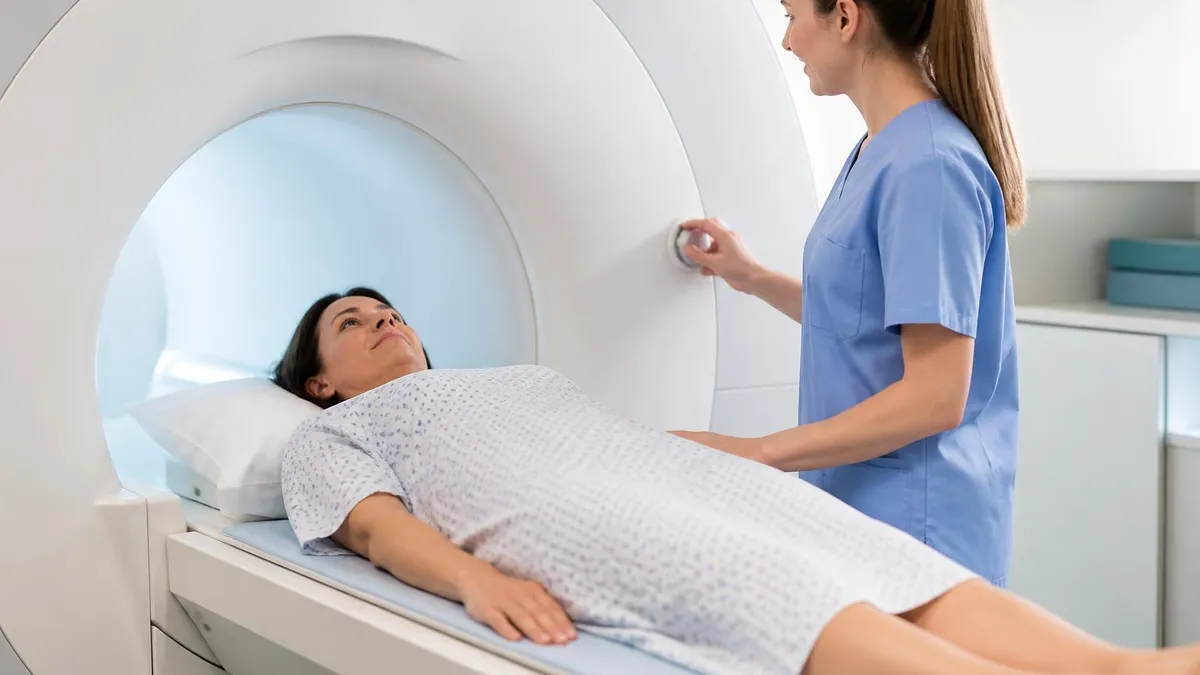
From the patient's point of view, entering the MRI bore means sliding into a smooth, white, well-lit cylindrical tunnel approximately 24 to 28 inches in diameter. Most modern systems include LED lighting strips along the bore walls, small ventilation fans that move air gently to prevent stuffiness, and a mirror or angled prism that allows the patient to see out of the bore toward the feet, reducing the sense of enclosure. Many facilities also offer headphones with music or a movie system projected onto the bore ceiling.
The interior walls of the bore are made from smooth fiberglass or composite material and are curved seamlessly from top to bottom. There are no visible mechanical components inside the bore itself — the gradient coils, the body RF coil, and the main magnet windings are all hidden behind the smooth inner lining. Patients will hear loud rhythmic banging, clicking, and buzzing as the gradient coils switch rapidly during each pulse sequence. A call bulb is placed in the patient's hand so they can signal the technologist at any moment, and an intercom allows two-way communication throughout the scan.
Closed-Bore vs. Open MRI: Comparing the Two Main Designs
- +Higher field strength (1.5T–3T) produces superior image quality and diagnostic detail
- +Shorter scan times due to stronger gradients and better signal-to-noise ratio
- +Wider range of clinical protocols available, including advanced neuroimaging and cardiac MRI
- +Preferred for oncology staging, functional MRI, and MR spectroscopy applications
- +Industry-standard for board examination curricula and clinical training programs
- +More widely available in community hospitals and outpatient imaging centers
- −The enclosed bore triggers claustrophobia in an estimated 5–10% of patients
- −Bore diameter limitations make scanning morbidly obese patients challenging or impossible
- −Louder gradient noise requires hearing protection and can cause patient anxiety
- −Longer setup and positioning times for complex coil configurations
- −Fringe magnetic field requires larger room footprint and more extensive shielding
- −Higher purchase and installation cost compared to open MRI alternatives
MRI Room Setup and Visual Safety Checklist
- ✓Confirm the four-zone safety boundary system is posted on all entrance doors to the MRI environment.
- ✓Verify that Zone III and Zone IV doors are secured and accessible only to trained MRI personnel.
- ✓Check that ferromagnetic detection system (FMDS) is active and calibrated at the Zone III entry point.
- ✓Inspect the scan room floor for any unsecured metallic objects before each patient session.
- ✓Confirm all surface coils are free of visible damage, frayed cables, or cracked housings before use.
- ✓Ensure the patient table weight capacity placard is visible and within safe operating limits for the scheduled patient.
- ✓Verify emergency quench button covers are intact and the button is accessible but protected from accidental activation.
- ✓Confirm bore lighting and ventilation fans are operational before positioning any patient inside the magnet.
- ✓Check that the patient communication intercom and emergency call bulb are functional at the start of each shift.
- ✓Verify cryogen vent pipe visual indicators show no signs of helium venting, which would indicate a quench event.
The Visible Machine Is Only a Small Part of the System
The scanner housing patients see represents less than 30% of the total MRI system infrastructure. The equipment room, cryogenic plumbing, RF shielding, and specialized electrical service together account for the majority of both the physical footprint and the installation cost. When studying MRI equipment, always think of the scanner as the centerpiece of a larger engineered environment — not a standalone device.
Magnetic field strength is the single most important technical specification that determines both the visual size of an MRI system and its diagnostic capability. A 1.5T clinical MRI scanner and a 3T scanner may look nearly identical to a patient walking into the scan room — both present the familiar white cylindrical housing, the padded patient table, and the smooth bore interior — but the engineering differences concealed within the housing are substantial and have direct consequences for image quality, scan speed, and the range of clinical applications the system can support.
The 1.5T magnet has been the workhorse of clinical MRI since the 1980s and remains the most widely installed field strength in community hospitals and outpatient imaging centers across the United States. The cryostat on a modern 1.5T system is engineered to be compact and lightweight relative to older designs, with some current models weighing as little as 4,000 to 5,000 kilograms.
The fringe magnetic field of a well-shielded 1.5T magnet may be actively contained to within the scan room itself using passive iron shielding in the walls or active magnetic shielding coils built into the magnet assembly — a technology that dramatically reduces the room size requirements compared to older unshielded designs from the 1990s.
The 3T MRI scanner has become the preferred choice for academic medical centers, neuroimaging programs, and facilities with a high volume of musculoskeletal and breast MRI. Visually, 3T systems are often slightly larger and heavier than comparable 1.5T systems — a typical 3T magnet assembly weighs between 8,000 and 13,000 kilograms — and they require more extensive room shielding due to the stronger fringe field.
The five-gauss line, which defines the safety boundary within which unsupported persons with pacemakers should not enter, extends further from the magnet in 3T installations even with active shielding, and this influences the size of the scanning suite and the safety zone layout that staff and visitors must navigate.
Ultra-high-field MRI at 7 Tesla is approved in the United States by the FDA for brain, spine, and knee imaging and is increasingly available at major academic institutions. A 7T scanner is visually imposing: the magnet cryostat is substantially larger and heavier than a 3T system, often exceeding 25,000 to 30,000 kilograms, and requires purpose-built structural reinforcement of the floor and walls.
The bore of early 7T systems was 60 centimeters — the same as a traditional closed-bore system — but newer designs have expanded to 68 centimeters to improve patient access. The raw power of a 7T magnet means that any ferromagnetic object brought within its proximity becomes an extreme projectile hazard at much greater distances than lower-field clinical systems, requiring exceptionally rigorous access control.
Low-field and ultra-low-field MRI represents an emerging category on the opposite end of the field-strength spectrum. Systems operating between 0.064T and 0.5T — including some portable bedside units — have a dramatically different visual profile. Some portable low-field systems are small enough to be wheeled on a cart to a patient's bedside in an intensive care unit, neurology ward, or even an emergency department, avoiding the time and logistical challenges of transporting critically ill patients to a fixed MRI suite.
These units often resemble a large C-arm fluoroscopy device more than a conventional MRI scanner, with an open magnet assembly positioned around the patient's head or affected limb while the rest of the equipment sits on a rolling cart beside the bed.
Hyperpolarized MRI systems represent another specialized category. These installations combine a standard 1.5T or 3T clinical scanner with a separate hyperpolarizer device — which looks like a large laboratory instrument or small refrigerator placed in an adjacent room — that prepares metabolic tracers such as hyperpolarized carbon-13 pyruvate for injection and imaging. The MRI scanner itself appears identical to any other clinical 1.5T or 3T system, but the workflow and room setup are radically different, with the hyperpolarizer, warm-up protocols, and rapid injection timing requirements adding significant complexity to the scanning environment.
Understanding how field strength relates to machine appearance and capability is fundamental knowledge for anyone pursuing ARRT certification in MRI. Registry examination questions frequently ask candidates to identify appropriate field strengths for specific clinical applications, understand the safety implications of different field levels, and recognize how magnet design choices affect patient throughput, image quality, and the operational demands placed on the scanning team. This knowledge base builds directly on the ability to visually identify and functionally understand each component of the MRI system as a whole.
The MRI magnet is always on — even when no scan is in progress. Any ferromagnetic object brought into Zone IV can become a dangerous projectile accelerated toward the bore at high speed. Visual warning signs, color-coded floor markings, and ferromagnetic detection systems are all physical safety features you will see in a properly configured MRI suite. Never assume a room is safe because it looks empty.
The safety zone system in a clinical MRI facility is not merely a regulatory formality — it is a visible, physically designed architecture that shapes the layout of every room in the MRI environment and defines the boundaries patients, staff, and visitors must observe to interact safely with the powerful magnetic field. The American College of Radiology defines four safety zones in its MRI safety guidelines, and each zone has a distinct visual character that experienced technologists and radiologists recognize immediately upon entering any MRI facility in the United States.
Zone I is the general public area — the waiting room, corridors, and reception spaces outside the MRI suite where no magnetic hazard exists. Visually, Zone I looks like any other hospital or outpatient clinic waiting area: chairs, informational posters, a reception desk. The only MRI-specific visual element that may appear in Zone I is patient education materials explaining what to expect during the scan and a preliminary screening questionnaire distributed to all patients before they proceed further into the MRI environment.
Zone II serves as the transition corridor between the unrestricted public area and the restricted MRI environment. This is typically where the MRI technologist greets patients, reviews safety screening forms, changes patients into exam gowns, and stores personal belongings in secure lockers. Zone II rooms often feature prominent visual warnings — large wall-mounted signs depicting items prohibited beyond this point, including keys, wallets, watches, hearing aids, and medication patches — along with a ferromagnetic detection archway or wand screening station through which all patients and accompanying persons must pass before proceeding to Zone III.
Zone III is the restricted area immediately outside the scan room where the magnetic fringe field begins to have significant strength. The door to Zone III is typically secured by an access control system — a keypad, badge reader, or simple manual lock — and is marked with red or yellow warning signs indicating that access is restricted to MRI-trained personnel and pre-screened patients. Visual indicators may include floor markings delineating the five-gauss line, beyond which pacemaker patients must not pass, and mounted signs listing specific implants and devices that must be verified as MRI-compatible before entry.
Zone IV is the MRI scan room itself — the most restricted area in the facility and the one housing the magnet at full field strength. The room is visually distinct from any other clinical space: it is typically larger than a standard examination room, its walls may be visibly thicker if they contain passive iron shielding, and every surface and piece of equipment within the room is made from non-ferromagnetic materials.
The patient table, coil storage racks, oxygen delivery equipment, and any IV stands visible in the room are all constructed from aluminum, brass, titanium, or medical-grade plastic rather than the steel and iron used in standard medical equipment.
The visual cues associated with magnet quench management are also important for anyone working in or studying the MRI environment. A quench pipe — a large-diameter tube, typically four to eight inches in diameter, made of insulated metal — runs from the magnet housing through the ceiling or wall to an exterior vent where helium gas can be safely released in the event of a quench.
The presence and condition of this vent pipe is one of the first things an MRI site planner checks during a facility inspection, and its visual routing through the room often influences the layout of furniture, coil storage, and emergency access paths within Zone IV.
Color-coded warning systems, internationally standardized pictogram signs, and physical barriers such as self-closing doors and magnetic field boundary floor markings all contribute to a layered visual safety architecture that reinforces the training MRI personnel receive. For students preparing for the ARRT MRI examination, being able to identify these visual safety elements, understand what they signify, and explain their purpose to patients and referring clinical staff is an essential competency that appears regularly in both didactic coursework and registry examination content.
For anyone preparing for the ARRT MRI certification examination, a thorough visual and functional understanding of MRI equipment is not just helpful background knowledge — it is directly tested content that appears across multiple domains of the registry examination blueprint. Questions about magnet design, coil types, gradient function, safety zones, and RF shielding appear in the Equipment Operation and Quality Control domain, which represents approximately 30% of the examination content. Studying MRI equipment by learning to recognize, name, and explain the function of each visible and hidden component is one of the most efficient ways to build examination-ready knowledge.
When studying the physical appearance and functional organization of an MRI system, begin with the main magnet and work outward. The superconducting magnet is the heart of the system — its field strength, bore size, and shielding design determine nearly every other characteristic of the installation.
Next, study the gradient coil system, understanding that the three gradient axes (frequency encoding, phase encoding, and slice selection) each correspond to a physical coil assembly that switches rapidly during imaging and produces the characteristic noise patients hear. Knowing that the loudest banging sequences correspond to the fastest gradient switching rates connects physical experience to technical knowledge in a way that helps both examination performance and patient communication skills.
Radiofrequency coil selection is another visually prominent and heavily tested aspect of MRI equipment knowledge. Different coil types — volume coils, surface coils, phased-array coils, and endorectal coils — have very different physical appearances and are selected based on the anatomy being imaged, the required field of view, and the signal-to-noise ratio needed for the clinical indication.
A head coil resembles a rigid helmet or birdcage; a spine coil is a flat, segmented array built into the patient table; a shoulder coil wraps around the joint like a padded sleeve. Learning to identify each coil type visually and understand its clinical application is a skill that bridges the examination room and the clinical environment.
Practice test questions on MRI equipment often present scenarios where a technologist must choose between scanner configurations, troubleshoot image artifacts related to coil positioning or equipment malfunction, or explain a feature of the MRI room to a patient or referring clinician. Building a mental visual model of the complete MRI environment — from the control room console through the Zone III corridor, into the Zone IV scan room, and back to the equipment room — gives you a cognitive framework for reasoning through these scenario-based questions even when the specific technical detail is unfamiliar.
Simulation and virtual reality training tools are increasingly used in MRI technology programs to help students build this visual familiarity before their first clinical rotation. These platforms allow students to virtually walk through a complete MRI suite, interact with scanner controls, position simulated patients, and practice responding to emergency scenarios such as a patient pressing the call bulb mid-scan or a metallic object being carried toward the bore. Students who have used these tools consistently report higher confidence on their first clinical rotation day and score higher on equipment-related examination items.
Study groups and peer review are particularly effective for visual equipment knowledge because verbal description and diagram comparison help cement spatial relationships between components. Drawing a floor plan of a standard MRI suite — labeling Zones I through IV, marking the location of the main magnet, equipment room, control room, quench pipe, ferromagnetic detection system, and emergency stop buttons — is a classic and highly effective study technique that many successful candidates report using in the weeks before the registry examination.
Finally, supplementing textbook study with facility tours, YouTube walkthroughs from academic MRI programs, and manufacturer product videos gives you exposure to real-world variation in scanner design and room layout that examination items occasionally reference. No two MRI installations are identical, but the underlying components, safety principles, and operational workflows are consistent across systems and are the foundation on which all registry examination content is built. The more vividly you can picture a real MRI environment when you read an examination question, the more effectively you can apply your technical knowledge to arrive at the correct answer.
MRI Questions and Answers
MRI of Cervical Spine: Complete Guide to Imaging, Anatomy, Pathology, and Patient Preparation
Knee MRI Images: A Complete Guide to Reading, Understanding, and Interpreting Knee Scans

Ace Your Exam with MRI Practice Test 2026 Prep

MRI Tech School 2026 — Programs, Requirements, and What to Expect

Man Dies in MRI Machine: Understanding MRI Safety Incidents, Risks, and Prevention
About the Author

Medical Laboratory Scientist & Clinical Certification Expert
Johns Hopkins UniversityDr. Sandra Kim holds a PhD in Clinical Laboratory Science from Johns Hopkins University and is certified as a Medical Technologist (MT) and Medical Laboratory Scientist (MLS) through ASCP. With 16 years of clinical laboratory experience spanning hematology, microbiology, and molecular diagnostics, she prepares candidates for ASCP board exams, MLT, MLS, and specialist certification tests.
Join the Discussion
Connect with other students preparing for this exam. Share tips, ask questions, and get advice from people who have been there.
View discussion (8 replies)