MRI Machine Pictures: A Complete Visual Guide to MRI Scanner Types, Components, and Imaging Equipment
Explore MRI machine pictures and learn about scanner types, components, magnet strengths, and what each part of an MRI system looks like. ✍🏼
When people search for mri machine pictures, they are often trying to visualize what an MRI scanner actually looks like before walking into an imaging suite, preparing for a procedure, or studying radiologic technology. The photos that circulate online range from sleek closed-bore tunnel magnets in modern hospitals to wide-bore systems designed for claustrophobic patients, open MRI scanners that resemble parallel plates, and compact extremity units that scan only a wrist or knee. Each image tells a different story about magnet strength, patient comfort, and clinical purpose.
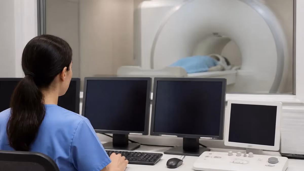
An MRI machine is far more than the donut-shaped tube most people picture. Behind the visible bore sits a superconducting magnet cooled by liquid helium, a network of gradient coils, radiofrequency transmitters, and a shielded room that blocks external electromagnetic interference. Pictures of MRI machines often show the patient table, the operator console in an adjacent room, and the cryogen quench pipe running through the ceiling. Understanding what each visible part does helps demystify the technology behind every scan.
For students preparing for registry exams, technologists training on new equipment, or patients researching their upcoming appointment, visual references matter. Reviewing the history of MRI alongside modern equipment photos reveals how dramatically the technology has evolved since Raymond Damadian's 1977 prototype. Today's scanners are quieter, faster, and capable of producing images at field strengths ranging from 0.2 Tesla open systems to 7 Tesla research magnets.
This visual guide walks through the major MRI machine categories you'll encounter in clinical practice. We'll examine closed-bore versus open designs, explain field strength differences, and break down the recognizable components every technologist should identify on sight. You'll also see how scanner appearance correlates with diagnostic capability, patient throughput, and the types of exams the equipment can perform safely and effectively.
Beyond aesthetics, MRI machine pictures serve a practical educational role. Manufacturers like Siemens, GE Healthcare, Philips, Canon, and Hitachi each produce distinctive scanner designs with unique gantry shapes, table configurations, and coil mounting systems. Recognizing these visual differences helps technologists transition between facilities, supports patient education conversations, and aids radiology students in identifying equipment during clinical rotations or board examinations.
Whether you are a prospective MRI technologist, a curious patient, a radiology student, or simply someone fascinated by medical pet mri, this comprehensive visual reference will help you understand what you're looking at when you see an MRI machine photo. We'll cover scanner anatomy, manufacturer differences, safety zone signage, coil varieties, and the supporting infrastructure that makes mri with vs without contrast possible. By the end, the next mri machine pictures you encounter will tell a much richer story.
Use this article as both a learning resource and a reference. Each section connects visual cues to functional purpose, giving you the vocabulary and anatomy needed to discuss MRI equipment with confidence. Practice quizzes throughout the page reinforce key concepts, while related articles expand on specialized topics like contrast imaging, safety protocols, and outpatient facility design.
MRI Machines by the Numbers
MRI Scanner Types and Designs
The most common scanner design, featuring a tunnel-shaped bore typically 60-70 cm in diameter. Produces the highest image quality and supports field strengths from 1.5T to 7T for research applications.
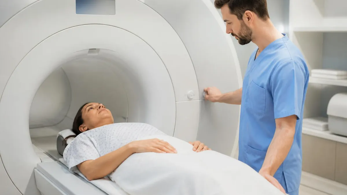
Functionally identical to closed-bore scanners but with a 70 cm opening to reduce claustrophobia. These systems accommodate larger patients up to 550 pounds while maintaining 1.5T or 3T diagnostic image quality.
Feature an H-shaped or C-shaped design with no enclosed tunnel, ideal for claustrophobic, pediatric, and bariatric patients. Field strengths are typically lower at 0.2T to 1.2T with reduced image resolution.
Compact scanners designed exclusively for arms, legs, wrists, knees, or feet. Patients sit beside the machine while only the limb enters the small bore, eliminating whole-body claustrophobia concerns entirely.
Specialized scanners installed in surgical suites for real-time imaging during neurosurgery and tumor resection. Often mounted on ceiling rails to move toward the patient rather than the patient moving to the magnet.
Magnet strength is the single most important specification when evaluating mri machine pictures, because it determines image resolution, scan speed, and clinical applications. MRI field strength is measured in Tesla (T), named after inventor Nikola Tesla, with one Tesla equaling 10,000 gauss. For context, Earth's magnetic field measures roughly 0.5 gauss, meaning a standard 1.5T clinical MRI generates a field 30,000 times stronger than the planet's natural magnetism. This explains why safety zones and ferromagnetic screening are so critical around any installed scanner.
Low-field MRI systems operate between 0.2T and 0.5T and typically appear in photos as open or C-shaped designs. These scanners use permanent magnets or resistive electromagnets rather than superconducting coils, which means they don't require liquid helium cooling. The trade-off is longer scan times and lower spatial resolution, but they excel for claustrophobic patients, pediatric imaging, and extremity studies. Recent advances have brought portable point-of-care 0.064T units to bedsides and emergency departments.
Mid-field scanners between 0.6T and 1.0T occupy a smaller market share but still appear in some outpatient facilities. The workhorse of dwi mri remains the 1.5T closed-bore system, which balances image quality, scan efficiency, and patient throughput. Walking through any major hospital's imaging department, you'll likely see multiple 1.5T units handling everything from routine brain MRIs to musculoskeletal exams, abdominal imaging, and cardiac studies.
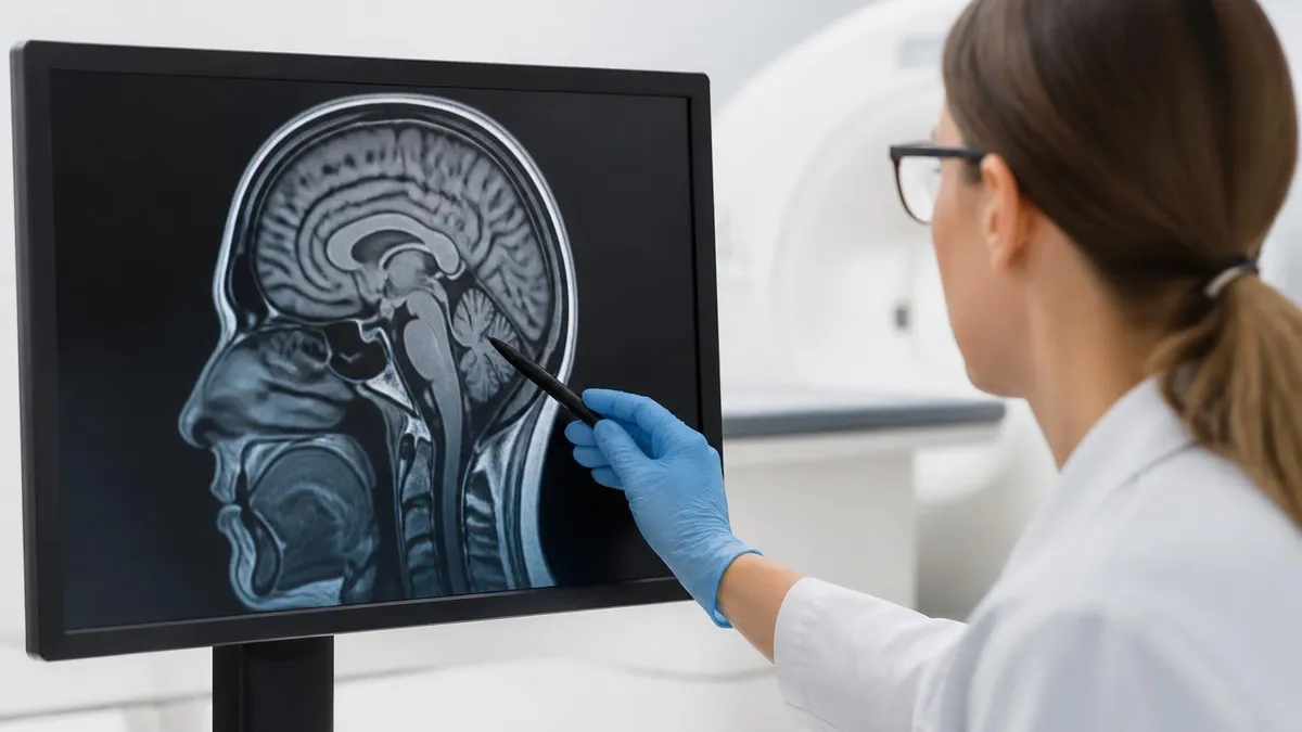
The 3T scanner has become increasingly common over the past fifteen years and now represents the standard for neuroimaging, prostate MRI, and advanced research applications. Photos of 3T systems often show heavier shielding, larger gradient cabinets in equipment rooms, and more sophisticated cooling infrastructure. The doubled field strength produces signal-to-noise ratios roughly twice that of 1.5T systems, enabling thinner slices, faster acquisitions, and higher diagnostic confidence for subtle pathology.
Ultra-high-field systems at 7T and above remain primarily research tools, though FDA clearance for 7T clinical use arrived in 2017. These scanners require massive shielding, dedicated power infrastructure, and specialized RF coils. Pictures of 7T installations often show distinctive cryogen quench pipes, reinforced room construction, and isolation from other building systems. The image quality is breathtaking for brain and musculoskeletal imaging, but artifacts and safety considerations limit broader clinical deployment.
When reviewing mri machine pictures across different field strengths, look for visual clues that hint at magnet power. Higher field systems tend to have longer bore lengths, more substantial gantry housings, and more visible cooling infrastructure. Many facilities post the Tesla rating directly on the scanner exterior or on safety signage at the entrance to the magnet room. Understanding these visual cues helps technologists and students quickly identify equipment capabilities. For patients preparing for an exam, learning about MRI with and without contrast protocols at different field strengths can clarify what to expect.
Field strength also affects acoustic noise levels visible in scanner design. Higher-field systems require more powerful gradient coils, which generate louder sounds during image acquisition. Modern pictures often show built-in noise reduction technologies, integrated headphones, and patient communication systems. Some manufacturers have introduced quiet sequences that reduce gradient noise by up to 80 percent, making the patient experience significantly more comfortable regardless of magnet strength.
MRI Practice Test Questions
Prepare for the MRI - Magnetic Resonance Imaging exam with our free practice test modules. Each quiz covers key topics to help you pass on your first try.
MRI Knowledge
MRI Exam Questions covering Knowledge. Master MRI Test concepts for certification prep.
MRI Physics
Free MRI Practice Test featuring Physics. Improve your MRI Exam score with mock test prep.
MRI Anatomy and Pathology
MRI Test Prep for MRI Anatomy and Pathology. Practice MRI Quiz questions and boost your score.
MRI Anatomy and Positioning
MRI Questions and Answers on MRI Anatomy and Positioning. Free MRI practice for exam readiness.
MRI Contrast Agents
Free MRI Quiz on MRI Contrast Agents. MRI Exam prep questions with detailed explanations.
MRI Patient Care and Positioning
MRI Practice Questions for MRI Patient Care and Positioning. Build confidence for your MRI certification exam.
Visual Components of an MRI Machine
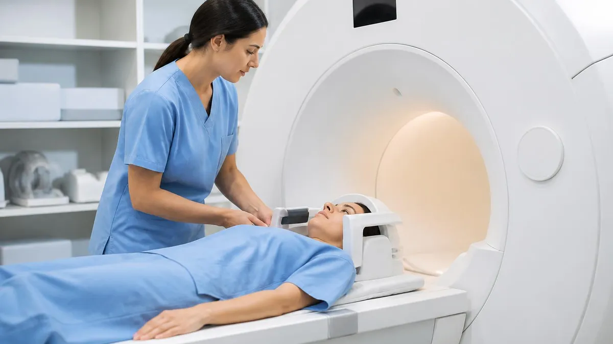
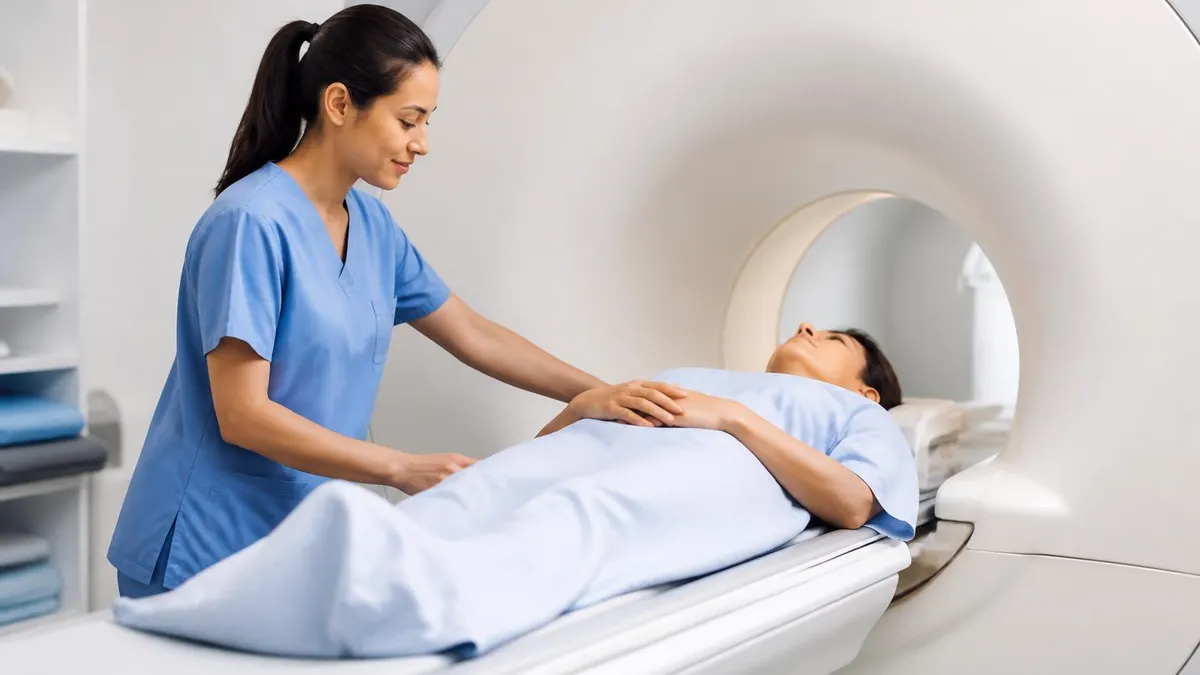
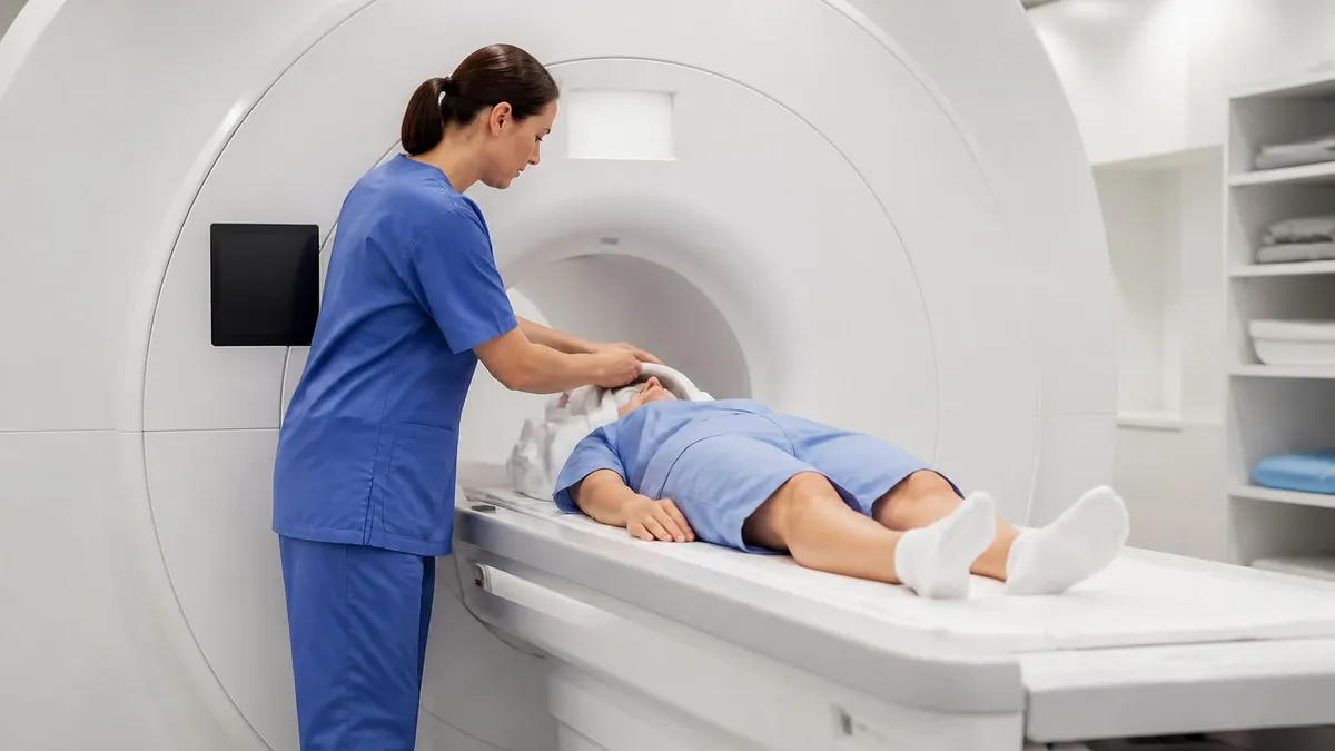
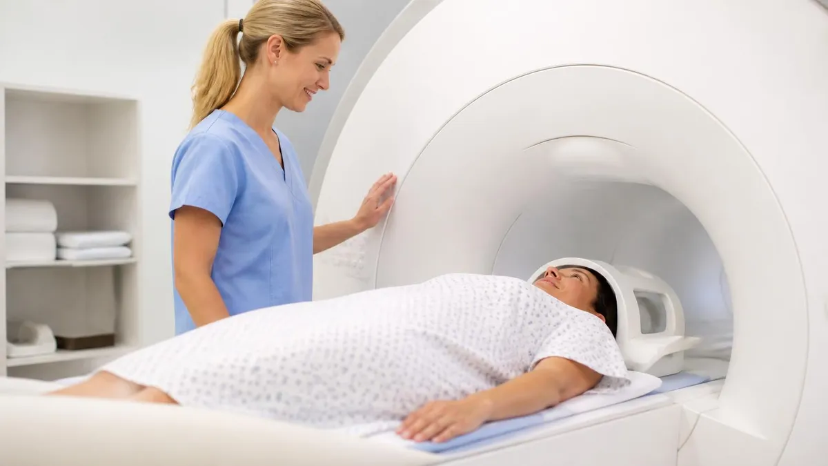
The external view of an MRI scanner reveals the gantry housing, patient table, and bore opening. The gantry is the large cylindrical or rectangular structure containing the magnet, gradient coils, and RF body coil. Most modern scanners feature a sleek plastic shroud in white or beige with colored accent stripes that often indicate the manufacturer. The patient table slides in and out of the bore on motorized rails and includes mattress pads, head rests, and coil mounting positions.
Look for the laser alignment system, typically a small red or green light projector mounted above the bore opening. This helps technologists position anatomy precisely at isocenter. You'll also see the patient communication speaker grille, status indicator lights showing scan state, and emergency stop buttons mounted on both sides of the gantry. Cable management trays running along the floor connect surface coils to ports built into the table or gantry housing.
Closed-Bore vs Open MRI: Visual and Clinical Comparison
- +Closed-bore systems produce significantly higher image resolution at 1.5T and 3T field strengths
- +Wide-bore designs at 70 cm accommodate claustrophobic patients while maintaining diagnostic quality
- +Modern closed-bore scanners feature ambient lighting, video displays, and noise reduction technology
- +Faster scan times reduce overall exam duration and improve patient throughput dramatically
- +Closed designs support advanced sequences like diffusion tensor imaging and functional MRI
- +Better signal-to-noise ratio enables thinner slices and more detailed pathology detection
- +Higher field strength supports specialized exams including cardiac, prostate, and breast MRI
- −Traditional closed-bore tunnels can trigger claustrophobia in approximately 5-10% of patients
- −Higher field systems generate louder gradient noise during image acquisition sequences
- −Closed-bore weight limits typically max out around 350-500 pounds depending on table design
- −Open MRI offers better access for interventional procedures but with reduced image quality
- −Low-field open systems may miss subtle pathology that requires high-resolution detection
- −Open scanners typically require longer scan times to compensate for weaker magnetic fields
- −Some advanced sequences are unavailable or limited on lower field strength open systems
How to Identify MRI Equipment in Pictures
- ✓Check the bore shape: cylindrical tunnel indicates closed-bore, C-shape or H-shape indicates open MRI
- ✓Measure approximate bore diameter visually: 60 cm standard, 70 cm indicates wide-bore design
- ✓Look for the manufacturer logo on the gantry housing or patient table for brand identification
- ✓Identify the laser alignment system above the bore for patient positioning reference
- ✓Spot the quench pipe rising from the magnet through the ceiling as a superconducting indicator
- ✓Note the patient communication speaker and emergency call button locations on the gantry
- ✓Observe coil ports built into the patient table for surface coil connections
- ✓Look for safety signage indicating Zone IV restrictions and field strength specifications
- ✓Check for RF-shielded window between magnet room and operator control area
- ✓Identify cryogen monitoring panels and gradient cabinets in adjacent equipment rooms
The Five-Second MRI Test
You can identify any MRI scanner in five seconds by checking three visual cues: bore shape (closed tunnel vs open C-shape), gantry depth (long indicates higher field strength), and quench pipe presence (confirms superconducting magnet). These three clues alone reveal field strength category, patient comfort profile, and clinical capability without reading a single specification label.
Major MRI manufacturers each produce distinctive scanner designs that become recognizable to experienced technologists. Siemens Healthineers dominates the global market with their MAGNETOM line, featuring sleek white gantries with subtle blue accent stripes and characteristic curved patient tables. The MAGNETOM Vida, Sola, and Lumina represent their current 1.5T and 3T flagship products, while the MAGNETOM Free.Max introduced the first 80 cm bore in 2021 specifically to accommodate bariatric and severely claustrophobic patients.
GE Healthcare scanners typically feature their signature beige and dark gray color scheme with rounded gantry corners. The SIGNA family includes the Architect, Premier, Pioneer, and Voyager models across various field strengths. GE pioneered the AIR Recon DL deep learning reconstruction technology and recently introduced the SIGNA Hero with a 70 cm open bore mri. Their patient tables often include distinctive integrated coil docking systems that streamline workflow for technologists during routine exams.
Philips Healthcare produces the Ingenia, Achieva, and Elition series scanners, often photographed with their characteristic dStream digital coil technology. Philips scanners frequently feature ambient experience lighting that projects calming images onto the bore interior to reduce patient anxiety. The Ambition X 1.5T system introduced sealed magnet technology that significantly reduces helium consumption from traditional 1,500 liters down to just 7 liters during installation and operation.
Canon Medical Systems, formerly Toshiba Medical, manufactures the Vantage Galan, Vantage Centurian, and Vantage Orian scanner lines. Canon emphasizes patient comfort with quieter Pianissimo gradient technology that reduces acoustic noise dramatically. Their scanners often appear in photos with white gantries and distinctive blue lighting accents. The compact gantry depth makes Canon systems easier to install in renovated suites with limited floor space requirements.
Hitachi (now part of Fujifilm) produces both open and closed-bore systems, with the Oasis and Aperto Lucent standing mri being widely photographed. These open systems use vertical-field permanent magnets and feature a distinctive parallel-plate design that maximizes patient access from all sides. Hitachi closed-bore systems include the Echelon series at 1.5T and 3T, often installed in community hospitals and outpatient imaging centers. Visit any modern MRI imaging centers location and you'll likely see one or more of these manufacturer designs.
Beyond the major players, specialty manufacturers produce niche equipment visible in mri machine pictures. Esaote makes dedicated extremity scanners like the O-scan and S-scan systems used in orthopedic clinics. Hyperfine introduced the Swoop portable 0.064T point-of-care scanner that rolls on wheels to patient bedsides in ICUs and emergency departments. Aspect Imaging produces compact neonatal MRI systems that fit directly into NICU rooms for the most fragile patients.
Recognizing manufacturer differences helps technologists transition between facilities and supports purchasing decisions for radiology departments. Each brand offers proprietary pulse sequences, coil designs, and user interfaces that affect daily workflow. Many MRI registry exam questions test the ability to identify equipment characteristics and understand how different platforms approach common imaging challenges. Building familiarity through both clinical experience and photo study pays dividends throughout an MRI technologist's career.
Never bring a camera, cell phone, or any electronic device into Zone IV of an MRI suite without prior safety screening. The magnetic field remains active 24/7 even when no patient is being scanned, and ferromagnetic objects can become dangerous projectiles. All facility photos of MRI machines must be taken with MR-conditional or non-ferromagnetic camera equipment, and all personnel must complete proper safety training before entry.
MRI safety zones are visible features in many facility photos and represent the four-tier access control system established by the American College of Radiology. Zone I is the general public area outside the imaging department, identifiable in photos by standard hospital flooring and signage. Zone II is the patient waiting and screening area where preliminary safety questionnaires are completed. Pictures of Zone II typically show changing rooms, lockers, and educational displays about the upcoming exam process.
Zone III is the controlled access area immediately adjacent to the magnet room. In photographs, you'll recognize Zone III by the prominent warning signs featuring the universal MRI safety symbol, magnetic field warnings, and ferromagnetic object restrictions. Access requires badge entry or escort by trained MRI personnel. The transition from Zone III to Zone IV is marked by heavy RF-shielded doors and clear floor markings indicating the boundary of the magnetic field danger zone.
Zone IV is the magnet room itself, where the static magnetic field exists at full strength. Photos of Zone IV always show prominent yellow and black warning signage, ferromagnetic detection systems at the entrance, and the iconic five-gauss line painted or marked on the floor. This line represents the boundary beyond which pacemakers, implanted devices, and other ferromagnetic objects pose serious risks. Modern facilities increasingly install ferromagnetic detection systems that scan personnel and equipment before entry.
The visual signage system in MRI suites follows standardized color coding and pictograms. Red warnings indicate prohibited items like oxygen cylinders, IV poles, and wheelchairs that aren't specifically MR-conditional. Yellow signs indicate caution areas and the static field boundary. Green indicators mark approved equipment and safe pathways. Understanding this color system is essential for both technologists and visitors entering the imaging environment for the first time.
Cryogen safety features appear prominently in many MRI machine pictures. The quench pipe is a large diameter duct that rises from the magnet through the ceiling and exits the building exterior. In an emergency quench, liquid helium rapidly converts to gas and vents through this pipe, preventing dangerous pressure buildup in the magnet room. Oxygen monitors mounted on the ceiling continuously measure room air quality and trigger ventilation systems if helium levels rise unexpectedly. For patients with implanted devices, reviewing the mri safety and compatibility before scheduling becomes essential.
Photographs of well-designed MRI suites also reveal supporting infrastructure that contributes to safety and image quality. The RF-shielded room construction uses copper or galvanized steel sheeting completely enclosing the magnet space. Special waveguides allow cables to pass through walls without compromising shielding integrity. Penetration panels concentrate all electrical and pneumatic connections at a single wall location, simplifying troubleshooting and maintenance access for service engineers.
Emergency equipment visible in MRI suite photos includes MR-conditional fire extinguishers, oxygen cylinders, and code carts designed specifically for the magnetic environment. Traditional aluminum or steel medical equipment cannot enter Zone IV safely. Specialized MR-conditional versions exist for nearly every clinical need, though they typically cost three to five times more than standard hospital equipment. Recognizing these specialized tools in photos helps trainees understand the scope of MRI-specific resource planning required at every imaging facility.
Putting your knowledge of mri machine pictures into practice requires moving beyond passive viewing toward active analysis. When you encounter scanner images in textbooks, manufacturer brochures, or facility marketing materials, train yourself to systematically identify components, estimate field strength, and predict clinical capabilities. This habit transforms casual viewing into meaningful study and prepares you for registry questions that test visual identification skills under timed conditions.
Begin each photo analysis with a structured approach: identify the scanner type first (closed, wide, open, or extremity), then estimate field strength based on visible cues, then locate key safety and support components. Note the patient table design, coil mounting options, and any visible accessories like contrast injectors or physiological monitoring equipment. This systematic method ensures you don't overlook important details that might appear on exams or affect clinical decision-making in real practice.
For students preparing for ARRT MRI certification, photo-based questions appear regularly on the registry examination. The exam may show an unidentified scanner and ask about field strength, appropriate patient populations, or typical clinical applications. Practice with manufacturer image libraries, professional society educational resources, and clinical rotation observations builds the visual recognition skills that distinguish confident candidates from those who hesitate when questions deviate from textbook descriptions.
Working technologists benefit from staying current with new scanner models through manufacturer educational materials and trade publications like RT Image, AuntMinnie, and Radiology Today. These resources publish detailed photographs of newly released equipment along with technical specifications and clinical workflow implications. Subscribing to manufacturer newsletters and attending RSNA, ISMRM, or SMRT conferences provides direct access to scanner imagery and hands-on demonstrations that supplement daily clinical experience.
Patients researching their upcoming exam benefit from facility websites that include scanner photographs along with descriptions of the patient experience. Knowing what to expect visually reduces anxiety significantly, particularly for first-time patients or those with claustrophobia concerns. Many imaging centers now post virtual tour videos that walk patients through arrival, screening, gowning, and the actual scan environment before they ever step foot in the building.
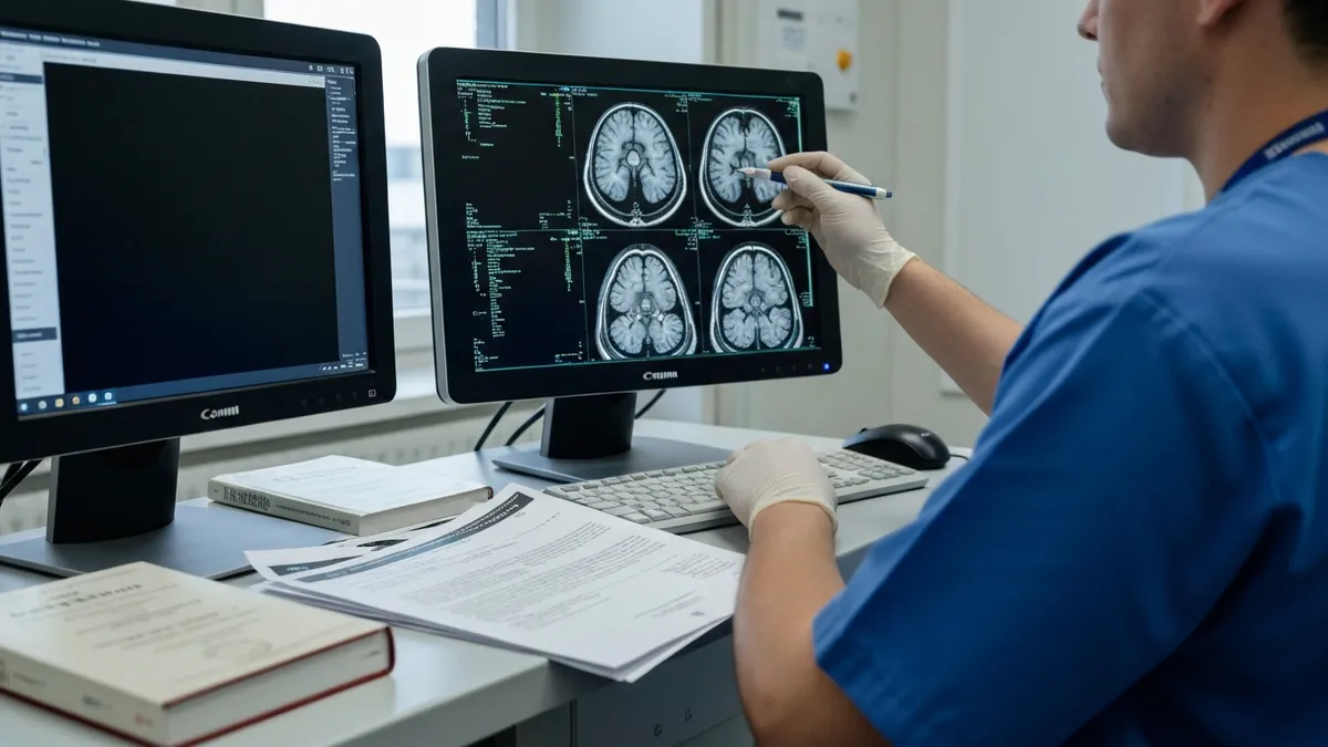
For radiology residents and fellows, recognizing scanner generation and capability affects image interpretation. Older 1.0T or 1.5T images differ visibly from modern 3T acquisitions in resolution, signal characteristics, and artifact patterns. Understanding what equipment produced an image helps contextualize what you're seeing on the workstation and informs decisions about whether to recommend repeat imaging at a different facility with more advanced technology when subtle findings require confirmation.
Building a personal reference library of mri machine pictures can accelerate learning significantly. Save manufacturer brochures, take notes during clinical rotations, and photograph (when permitted) the equipment at each facility you work in. Compare scanner appearances side by side to internalize the visual differences between brands, generations, and field strengths. Over time, identification becomes automatic, freeing mental energy for the more complex clinical decisions that define expert MRI practice throughout a successful technologist career.
MRI Questions and Answers
The History of MRI: From Discovery to Modern Medicine
MRI With and Without Contrast: How It Works, What to Expect
MRI Medical Abbreviation: What MRI Stands For and Why It Matters
MRI Imaging Centers: Complete Guide to Independent Outpatient MRI Facilities

St Jude Pacemaker MRI Compatibility List: A Complete Safety and Scanning Guide
About the Author
Medical Laboratory Scientist & Clinical Certification Expert
Johns Hopkins UniversityDr. Sandra Kim holds a PhD in Clinical Laboratory Science from Johns Hopkins University and is certified as a Medical Technologist (MT) and Medical Laboratory Scientist (MLS) through ASCP. With 16 years of clinical laboratory experience spanning hematology, microbiology, and molecular diagnostics, she prepares candidates for ASCP board exams, MLT, MLS, and specialist certification tests.
Join the Discussion
Connect with other students preparing for this exam. Share tips, ask questions, and get advice from people who have been there.
View discussion (6 replies)