
HVAC Gauge: The Complete Guide to Manifold Gauges, Refrigerant Pressure, and System Diagnostics
Learn how to use an HVAC gauge set to diagnose refrigerant pressure, identify system faults, and pass your HVAC certification exam. 📝
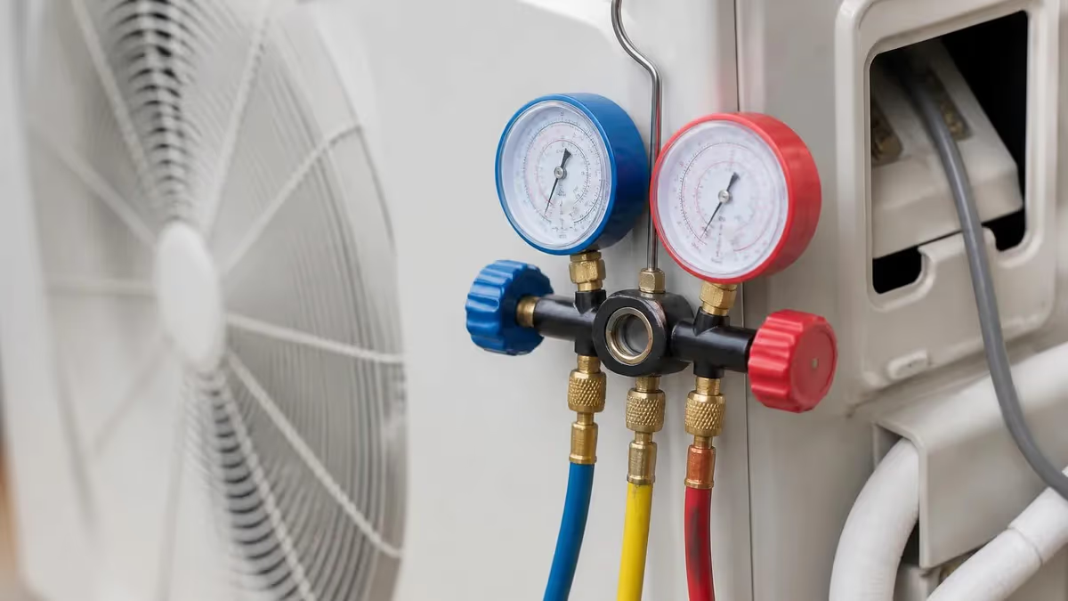
An HVAC gauge — more precisely called a manifold gauge set — is the single most important diagnostic tool in any heating and cooling technician's toolkit. Whether you are checking refrigerant charge on a residential split system, diagnosing a commercial chiller, or preparing for your EPA 608 certification exam, understanding how to read and interpret gauge pressures is a foundational skill. The manifold set gives you a real-time window into what is happening inside a sealed refrigerant circuit, translating invisible pressure and temperature relationships into numbers you can act on immediately.
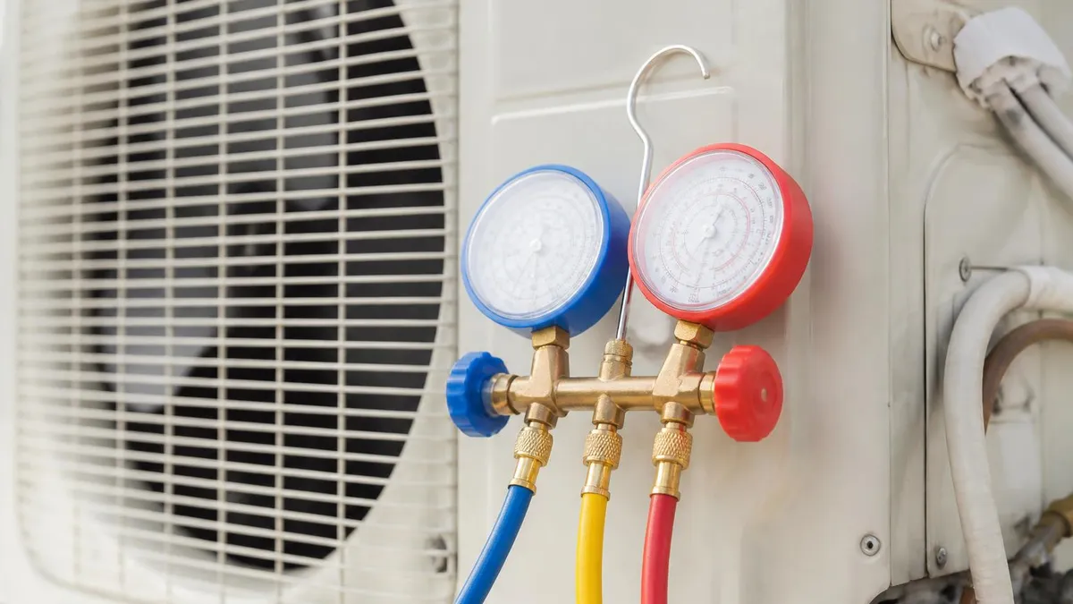
The classic analog manifold gauge set consists of two gauges mounted on a central manifold body: a low-side (blue) gauge and a high-side (red) gauge. Each gauge connects to the corresponding service port on the system through color-coded hoses. A third center port on the manifold connects to the refrigerant cylinder or a recovery machine. Modern digital manifold gauge sets add wireless Bluetooth connectivity, built-in temperature clamp sensors, and smartphone apps that log readings over time — but the underlying pressure measurement principles remain exactly the same as they were decades ago.
Refrigerant pressure readings mean nothing in isolation. A technician must always correlate gauge readings with the saturation temperature of the refrigerant being used, and then compare that saturation temperature to the actual air or water temperature entering the coil. This relationship — known as suction superheat on the low side and subcooling on the high side — tells you whether the system is properly charged, whether the metering device is functioning correctly, and whether there are airflow or heat transfer problems affecting system efficiency. Missing even one of these data points leads to misdiagnosis and costly repeat service calls.
Reading an hvac gauge correctly also requires understanding compound gauges. The low-side gauge is a compound gauge because it reads both pressure (in psig, pounds per square inch gauge) above atmospheric and vacuum (in inches of mercury, inHg) below atmospheric. This dual scale allows the same gauge to read system operating pressures during normal operation and to verify deep vacuum during the evacuation process before a system is charged with refrigerant. A high-quality low-side gauge should be able to read down to 30 inHg of vacuum, which corresponds to approximately 29.92 inHg at sea level — essentially a perfect vacuum.
Gauge accuracy and maintenance matter enormously in the field. A gauge that reads even two psig high or low on the low side can cause a technician to add refrigerant to a properly charged system, pushing it into overcharge and damaging the compressor over time. Manifold gauges should be zeroed regularly, kept clean, and protected from physical shock. Hoses must be leak-free and rated for the maximum working pressure of the refrigerants being handled. For high-pressure refrigerants like R-410A, hoses must be rated to at least 800 psig working pressure, with burst ratings well above 3,000 psig.
Digital manifold gauge sets have become the professional standard for good reason. They eliminate parallax reading errors, automatically look up saturation temperatures from built-in refrigerant tables, calculate superheat and subcooling in real time, and can connect wirelessly to a smartphone for data logging and report generation. Some units integrate micron gauges for vacuum measurement, eliminating the need for a separate tool. Entry-level digital manifolds from brands like Yellow Jacket, Fieldpiece, and Testo start around $200 to $400, while premium wireless sets with Bluetooth and cloud logging can cost $600 to $1,200 or more.
For students preparing for HVAC certification exams, gauge reading is one of the most heavily tested practical knowledge areas. Exam questions frequently ask about the relationship between suction pressure and evaporator coil temperature, proper superheat values for fixed-orifice versus thermostatic expansion valve systems, and the correct procedure for recovering refrigerant before opening a system. Building a strong conceptual understanding of how gauges work — not just memorizing numbers — is the best preparation strategy for both the written exam and real-world diagnostic work.
HVAC Gauge Use by the Numbers

Types of HVAC Manifold Gauge Sets
The traditional two-gauge manifold with color-coded hoses. Reliable, durable, and inexpensive, but requires technician to manually look up saturation temperatures and calculate superheat and subcooling using refrigerant pressure-temperature charts.
Electronic manifold with LCD or touchscreen display. Automatically calculates saturation temperature, superheat, and subcooling from built-in refrigerant tables. Eliminates parallax errors and supports data logging for documentation and trend analysis.
Advanced digital manifold that connects to a smartphone or tablet via Bluetooth. Technician views live readings on a large screen, logs data to the cloud, and generates customer-ready service reports without returning to the gauge set between readings.
Measures both positive pressure in psig and vacuum in inches of mercury. Essential for reading suction pressure during operation and verifying deep system evacuation before charging. Always the blue gauge on a standard manifold set.
Reads discharge pressure only, ranging from 0 to 800 psig or higher depending on refrigerant. Always the red gauge. High-side readings combined with outdoor ambient temperature allow calculation of subcooling, the key measure of refrigerant charge adequacy.
Understanding the relationship between refrigerant pressure and temperature is the foundation of all gauge-based diagnostics. Every refrigerant has a unique pressure-temperature (PT) relationship at saturation — the point where the refrigerant exists as a mixture of liquid and vapor simultaneously. At saturation, a specific pressure always corresponds to a specific temperature, and this relationship is fixed by the laws of thermodynamics. For R-410A, a suction pressure of approximately 120 psig corresponds to a saturation temperature of about 40°F, which is a typical evaporator coil operating point on a well-functioning residential air conditioner.
On the low side of the system, the suction pressure reading tells you what temperature the refrigerant is boiling at inside the evaporator coil. If that saturation temperature is significantly lower than the temperature of the air entering the coil, you know the refrigerant is absorbing heat and evaporating as designed. If the saturation temperature is too low — say 20°F when it should be 35°F — you may be looking at low airflow across the coil, a dirty evaporating coil, or an overcharged system that is flooding the suction line with liquid refrigerant instead of superheated vapor.
Superheat is the number of degrees the suction vapor has risen above its saturation temperature by the time it exits the evaporator coil and reaches the compressor. This measurement protects the compressor from liquid slugging, which occurs when liquid refrigerant enters the compressor and causes catastrophic mechanical damage.
Target superheat values vary by system type: fixed-orifice (piston or capillary tube) systems typically target 10°F to 18°F of suction superheat, measured at the suction service valve. Thermostatic expansion valve (TXV or TEV) systems typically target 10°F to 12°F superheat at the evaporator outlet, with system superheat measured at the suction service valve ranging from 20°F to 30°F depending on design.
On the high side, subcooling tells you how far the liquid refrigerant in the liquid line has cooled below its condensation point. A properly charged system with a functioning condenser and metering device typically shows 10°F to 20°F of subcooling. Low subcooling — below 5°F — usually indicates an undercharged system or a restriction upstream of the measurement point. High subcooling — above 20°F to 25°F — can indicate overcharge, a liquid line restriction, or a condenser that is operating exceptionally well due to cool ambient temperatures, high airflow, or both.
Taking accurate gauge readings requires careful attention to procedure. Connect hoses to service ports with the manifold valves fully closed before opening any valve. This prevents refrigerant from transferring between the high and low sides of the system through the manifold. On systems with Schrader valve service ports, the hose fitting depresses the Schrader valve core to allow pressure equalization the moment the hose is hand-tightened. Always purge hoses of non-condensables before connecting to a system being charged, especially when switching between refrigerant types or after returning from a recovery operation.
Temperature measurement complements pressure readings in every diagnostic workflow. A clamp-on thermocouple or thermistor probe placed on the suction line near the service valve gives you the actual suction line temperature, which you compare to the saturation temperature from the low-side gauge to calculate suction superheat. A liquid line temperature measurement near the condenser outlet gives you the liquid temperature for subcooling calculation. Without accurate temperature data alongside pressure data, gauge readings cannot yield meaningful conclusions about system charge or performance.
Modern digital manifolds simplify this process considerably by accepting direct thermocouple inputs. Once you enter the suction line clamp temperature and the liquid line temperature into the digital manifold, it calculates superheat and subcooling automatically and displays both values on screen alongside the pressure readings. Some advanced models also display the target superheat range for the selected refrigerant and system type, alerting the technician with a color-coded indicator if the measured value falls outside the acceptable window. This level of automation reduces diagnostic errors and speeds up service calls significantly.
HVAC Practice Test Questions
Prepare for the HVAC - Heating Ventilation and Air Conditioning exam with our free practice test modules. Each quiz covers key topics to help you pass on your first try.
HVAC Air Conditioning
HVAC Exam Questions covering Air Conditioning. Master HVAC Test concepts for certification prep.
HVAC Code Compliance
Free HVAC Practice Test featuring Code Compliance. Improve your HVAC Exam score with mock test prep.
HVAC Electrical Controls
HVAC Test Prep for Electrical Controls. Practice HVAC Quiz questions and boost your score.
HVAC Energy Efficiency
HVAC Questions and Answers on Energy Efficiency. Free HVAC practice for exam readiness.
HVAC Heating Systems
HVAC Mock Test covering Heating Systems. Online HVAC Test practice with instant feedback.
HVAC Load Calculations
Free HVAC Quiz on HVAC Load Calculations. HVAC Exam prep questions with detailed explanations.
HVAC Tools and Equipment
HVAC Practice Questions for HVAC Tools and Equipment. Build confidence for your HVAC certification exam.
HVAC Refrigeration
HVAC Test Online for Refrigeration. Free practice with instant results and feedback.
HVAC Safety Practices
HVAC Study Material on Safety Practices. Prepare effectively with real exam-style questions.
HVAC System Design
Free HVAC Test covering System Design. Practice and track your HVAC exam readiness.
HVAC Thermodynamics
HVAC Exam Questions covering Thermodynamics. Master HVAC Test concepts for certification prep.
HVAC Gauge Diagnostics: Superheat, Subcooling & Vacuum
Suction superheat is the primary indicator of evaporator performance and refrigerant charge adequacy on fixed-orifice systems. To measure it, read the low-side gauge pressure, look up the corresponding saturation temperature on a PT chart (or read it directly from a digital manifold), then clamp a temperature probe onto the suction line at the service valve. Subtract the saturation temperature from the measured line temperature. A result of 10°F to 18°F is normal for piston and capillary tube systems running R-410A or R-22 equivalents.
Low superheat — below 5°F — signals that liquid refrigerant may be reaching the compressor, a dangerous condition called flooding. This can result from overcharge, a stuck-open or oversized TXV, low load conditions such as a clean coil with excellent airflow, or a failed sensing bulb on a TXV system. High superheat — above 20°F to 25°F — typically points to undercharge, a clogged metering device, a restricted liquid line, or a TXV with a failed sensing bulb that has lost its charge pressure and is pinching closed.
Analog vs. Digital Manifold Gauge Sets: Which Should You Use?
- +Digital manifolds auto-calculate superheat and subcooling, eliminating PT chart lookup errors
- +Bluetooth connectivity allows readings to be logged remotely without returning to the gauge set
- +Built-in micron gauge port on some digital models eliminates a separate tool
- +Data logging supports professional service documentation and warranty compliance
- +Color-coded superheat and subcooling alerts reduce diagnostic errors on complex calls
- +Compatible with a wide range of refrigerants through regularly updated internal tables
- −Digital manifolds cost significantly more upfront than analog sets — often 3x to 5x the price
- −Battery dependency means a dead charge can end diagnostic capability mid-call
- −Software and firmware updates are required to add new refrigerant profiles over time
- −More complex to repair — a broken screen or failed sensor often means replacing the unit
- −Connectivity issues with Bluetooth or smartphone apps can frustrate field technicians
- −Over-reliance on automatic readings can prevent technicians from developing deep PT chart fluency
HVAC Gauge Connection and Diagnostic Checklist
- ✓Verify manifold gauge hoses are rated for the refrigerant and pressure of the system being serviced.
- ✓Close both manifold valves fully before connecting any hose to a system service port.
- ✓Purge hoses of air and non-condensables before connecting to a charged refrigerant system.
- ✓Record the refrigerant type on the unit data plate before setting up your digital manifold or PT chart.
- ✓Allow system pressures to stabilize for at least five minutes after connection before recording readings.
- ✓Clamp temperature probes onto suction and liquid lines and allow readings to stabilize before calculating superheat and subcooling.
- ✓Compare low-side saturation temperature to return air temperature entering the evaporator coil.
- ✓Compare high-side saturation temperature to outdoor ambient air temperature entering the condenser.
- ✓Check superheat against the manufacturer's target or the charging chart on the unit nameplate.
- ✓Document all pressure and temperature readings with timestamps for the service record.
One Degree of Subcooling Can Equal 1% Cooling Capacity
Research by ACCA and equipment manufacturers consistently shows that refrigerant charge errors of even 10% can reduce system efficiency by 5% to 10% and significantly increase compressor wear. Precise gauge readings and proper superheat and subcooling targeting are not just about passing an exam — they directly protect equipment longevity and customer energy bills on every service call you run.
Common gauge reading errors fall into several predictable categories, and learning to recognize them makes you a faster and more accurate diagnostician in the field. The first and most frequent mistake is reading pressures before the system has reached steady-state operation.
A system that has just started up will show transient pressures that fluctuate significantly for the first several minutes as the refrigerant redistributes and reaches equilibrium. Always allow five to ten minutes of runtime before recording diagnostic pressures, and more time — up to fifteen minutes — on large commercial systems or on equipment that was off for an extended period in cold weather.
A second common error is failing to account for altitude. Atmospheric pressure decreases as elevation increases, which affects the boiling point of refrigerants. At sea level, R-410A boils at approximately 120 psig at 40°F. At 5,000 feet of elevation, the same 120 psig reading corresponds to a slightly different saturation temperature because the reference point for gauge pressure (psig) changes. This effect is small — typically less than 1°F to 2°F on residential equipment — but it matters on precision work and in high-altitude markets like Denver or Albuquerque where HVAC technicians routinely work at elevations above 5,000 feet.
Refrigerant contamination is another scenario where gauge readings become misleading. Blended refrigerants like R-410A, R-407C, and R-404A have a glide — a range of temperatures over which they change state rather than a single point. If a blend is fractionated (partially leaked and then topped off, causing the remaining refrigerant to have a different composition than the original charge), the pressure-temperature relationship shifts unpredictably. A contaminated charge may show normal pressures while delivering subnormal cooling capacity, leading a technician to mistakenly add more refrigerant and worsen the problem. The correct fix is full recovery and recharge with virgin refrigerant.
Non-condensable gases — primarily air and nitrogen — cause high-side pressure to read higher than the saturation temperature alone would predict. When high-side pressure is improved but subcooling is also high and suction pressure is normal, the most likely explanation is non-condensables in the system.
The refrigerant is condensing at the correct temperature, but the additional partial pressure from the trapped air adds to the total high-side reading. The fix is to isolate the condenser, allow the refrigerant to migrate to the low side, and bleed the high side carefully through a recovery machine — never directly to atmosphere, as refrigerant venting is a federal offense under Clean Air Act Section 608.
Hose restrictions are a less obvious source of gauge errors that trap even experienced technicians. A hose with a partially blocked Schrader depressor, a kinked section, or an internal rubber deterioration that narrows the bore will show a pressure drop between the actual system pressure and the gauge reading.
Low-side hose restrictions cause the gauge to read lower than true system suction pressure; high-side restrictions cause it to read lower than true discharge pressure. The quickest diagnostic for a suspected restricted hose is to temporarily connect a known-good hose and compare readings. Hose restrictions become most apparent at higher flow conditions during refrigerant charging or recovery operations.
Gauge calibration drift is a real issue with analog instruments that have seen years of field use and physical shock. A gauge that reads 2 psig high on the low side will consistently make a well-charged system appear undercharged, leading the technician to add refrigerant on every call. Most HVAC supply houses and equipment manufacturers recommend re-zeroing analog gauges monthly and replacing any gauge that cannot be zeroed or that shows obvious needle damage.
Digital manifolds use electronic pressure transducers that are generally more stable over time, but they too can drift and should be verified against a known-accurate reference periodically, especially after the unit experiences a pressure spike from opening a high-side port without first equalizing pressure through the manifold.
Understanding these failure modes transforms you from a technician who reads gauges mechanically into a diagnostician who interprets what the gauges are telling you about the entire refrigerant circuit. The best field technicians develop an intuition for when gauge readings don't tell a coherent story — when high-side pressure seems too high for the outdoor temperature, when suction pressure is low but superheat is also low (a paradox that suggests low airflow rather than undercharge), or when pressures are fluctuating in a pattern that suggests a compressor valve leak cycling between adequate and inadequate compression on each stroke.

Releasing refrigerant intentionally into the atmosphere is a federal violation under EPA Section 608 of the Clean Air Act. Fines can exceed $44,539 per day per violation. Always recover refrigerant with a certified recovery machine before opening any part of a sealed refrigerant system, even for small repairs or gauge connection mistakes that result in accidental release.
HVAC certification exams — including the EPA 608, NATE (North American Technician Excellence), and state contractor licensing exams — place heavy emphasis on refrigerant gauge knowledge because proper gauge use is directly tied to environmental compliance, equipment protection, and customer safety. The EPA 608 exam has four sections: Core, Type I (small appliances), Type II (high-pressure refrigerants), and Type III (low-pressure refrigerants). Gauge reading, refrigerant handling, leak testing, evacuation procedures, and charging methods appear throughout all four sections, making gauge competency non-negotiable for certification.
On the EPA 608 Core exam, expect questions about the legal requirements for refrigerant recovery before system service, the minimum vacuum level required before charging (typically 500 microns in practice, though the exam may reference 1,000 microns as the older standard), the proper method for determining refrigerant charge using superheat versus subcooling, and the requirement to use recovery equipment that meets ARI 740 certification standards. Understanding why each requirement exists — not just what the rule says — helps you answer questions that are worded in unfamiliar ways or that present edge-case scenarios.
NATE certification exams go deeper into practical diagnostic application. The NATE Air Conditioning and Refrigeration specialty exams include scenario-based questions where you are given a set of gauge readings, temperature measurements, and system parameters, and must identify the most likely fault. For example, a question might describe an R-410A split system with a suction pressure of 95 psig, a discharge pressure of 420 psig, a suction line temperature of 55°F, and an outdoor ambient of 95°F, and ask you to identify the problem.
Working through the math — saturation temperature at 95 psig R-410A is approximately 32°F, giving superheat of 23°F, which is high; saturation at 420 psig is approximately 115°F, subcooling would need liquid line temperature to calculate — points toward undercharge or a restricted metering device as the most likely causes.
State contractor licensing exams in states like Florida, California, Texas, and New York often include trade knowledge sections that test refrigerant handling, gauge procedures, and charging calculations. These exams may use older refrigerants like R-22 in exam questions even though R-22 has been phased out of new production, because R-22 systems are still in service and licensed contractors must be able to service them legally using reclaimed refrigerant.
Knowing the PT relationships for both R-22 and R-410A, and understanding how the transition to newer lower-GWP refrigerants like R-32 and R-454B changes those relationships, gives you an edge on both legacy and emerging system questions.
Study strategies for gauge-related exam content should include heavy use of PT charts and charging calculators. Practice converting pressure readings to saturation temperatures by hand until you can estimate saturation temperatures for common refrigerants — R-22, R-410A, R-134a, R-404A — within a few degrees without looking at a chart. This mental fluency allows you to catch obviously wrong answer choices quickly and to spend more time on complex scenario questions. Online practice exams, like those available through PracticeTestGeeks, let you simulate the exam environment and identify knowledge gaps before test day.
Hands-on practice is irreplaceable for gauge mastery. If you are in an HVAC apprenticeship or training program, volunteer for every opportunity to connect manifold sets, take readings, and participate in charging procedures under supervision. If you are studying independently, consider purchasing a practice manifold and a set of training refrigerant cylinders to practice hose connections and PT chart lookups without working on live equipment.
Some HVAC training programs also offer refrigerant circuit simulators — benchtop units with actual compressors, condensers, and evaporators — that allow students to practice full diagnostic workflows including gauge connection, pressure reading, superheat calculation, and charging in a controlled environment.
Time management on certification exams matters as much as knowledge. Most EPA 608 exam formats allow approximately one minute per question. Gauge-related questions are often multi-step and require calculation, so practice working through superheat and subcooling problems quickly.
Use the process of elimination aggressively — if a question asks for the most likely cause of high suction pressure with low superheat, you can immediately eliminate undercharge (which would cause low suction pressure) and narrow your focus to the remaining choices. Building this diagnostic reasoning speed through timed practice is one of the highest-use study activities available before an HVAC certification exam.
Proper care and storage of HVAC gauge sets significantly extends their service life and protects measurement accuracy. After every service call, wipe manifold gauge faces with a clean cloth to remove oil, refrigerant residue, and dirt that can obscure dial markings or contaminate subsequent system connections.
Store manifold sets in their original case or a padded pouch to protect gauge faces and hose fittings from impact damage. Never allow hoses to kink sharply at the manifold connection — the reinforced section near the fitting is critical and repeated kinking at the same point will cause internal cracking that eventually leads to leaks or hose separation under pressure.
Refrigerant-specific hose color coding and labeling matters more than ever as the industry transitions to a wider variety of refrigerant types. While the traditional blue-for-low-side, red-for-high-side, and yellow-for-refrigerant color scheme remains standard for the manifold body and primary hoses, many technicians now use additional color-coded hose sets or labeled fittings to identify hoses dedicated to specific refrigerant families. Mixing refrigerant types through shared hoses can contaminate both the system being served and the recovery cylinder being used, creating costly disposal and recharge situations. Dedicated hose sets are an inexpensive insurance policy against cross-contamination.
Hose replacement is a maintenance task that many technicians defer too long. Hose inner liners deteriorate over time from exposure to refrigerant oil, pressure cycling, and UV light. A hose that appears externally sound may have interior degradation that causes it to absorb refrigerant into the wall material — a phenomenon called permeation — which contributes to the small but measurable refrigerant losses that accumulate across a fleet of service hoses used over months and years.
ASHRAE Standard 15 and EPA guidance both acknowledge permeation as a legitimate refrigerant loss pathway, but technicians can minimize it by choosing low-permeation hose materials and replacing hoses that show signs of softening, cracking at the fittings, or loss of flexibility in cold weather.
Field calibration verification is a professional habit that separates average technicians from elite diagnosticians. Before starting a detailed charging or diagnostic session on a critical system — a data center precision cooling unit, a medical facility chiller, or a restaurant walk-in where food safety depends on reliable temperature control — verify your manifold readings against a second trusted gauge set or a calibrated reference instrument. This two-minute step catches gauge drift before it causes a misdiagnosis, and it documents your due diligence if a warranty dispute arises later over the system charge state you verified at the time of service.
The transition to next-generation refrigerants is already changing the gauge requirements in the field. Refrigerants in the A2L category — mildly flammable blends like R-32, R-454B (the R-410A replacement chosen by many manufacturers), and R-32/R-125 blends — require attention to ignition source management during service.
While these refrigerants are not as flammable as propane or other A3 refrigerants, they can ignite under specific conditions, particularly if released in a confined space near an ignition source. Gauge handling procedures for A2L systems include ensuring adequate ventilation before connecting or disconnecting hoses, using recovery equipment rated for mildly flammable refrigerants, and never purging hoses by releasing refrigerant into the service area.
Training the next generation of HVAC technicians in gauge fundamentals is a responsibility that falls on journeymen and master technicians in the field, not just on classroom instructors. The best on-the-job learning happens when experienced technicians explain their reasoning aloud as they connect gauges, take readings, and interpret results — narrating the diagnostic process so apprentices understand not just what to do but why each step matters.
Building this culture of explanation and mentorship in HVAC service organizations improves diagnostic quality across the whole team and reduces the costly mistakes that happen when technicians work beyond their current skill level without asking for guidance.
Staying current with manufacturer charging procedures is equally important as mastering the fundamentals. Equipment manufacturers update their charging procedures as new refrigerants, coil designs, and control systems change the optimal target superheat and subcooling values for their specific equipment.
A TXV subcooling target of 10°F on a 2015 unit may be 15°F on a 2024 model from the same manufacturer due to changes in TXV sizing or coil surface area. Always locate and read the manufacturer's installation and service manual for the specific model being serviced before relying on generic industry targets. The information on the unit data plate and in the manufacturer's documentation takes precedence over any rule of thumb.
Related reading: hvac gauge covers the next step in more detail.
HVAC Questions and Answers
HVAC Sales: The Complete Guide to Selling Heating and Cooling Systems, Building Customer Trust, and Closing More Deals
HVAC Air Duct Sealing: The Complete Homeowner and Contractor Guide to Sealing Ductwork for Efficiency, Comfort, and Indoor Air Quality
HVAC Solutions: The Complete Guide to Heating, Cooling, and Indoor Air Quality Systems for Homes and Buildings

Commercial HVAC Repair: Systems, Costs, and Service Strategies
HVAC Apprenticeship Programs: Your Complete Guide to Starting a Hands-On Career in Heating, Ventilation, and Air Conditioning
About the Author

NATE Certified HVAC Technician & Licensing Exam Trainer
Universal Technical InstituteMike Johnson is a NATE-certified HVAC technician and EPA 608 universal-certified refrigerant handler with a Bachelor of Science in HVAC/R Technology. He has 19 years of commercial and residential HVAC installation and service experience and specializes in preparing technicians for NATE certification, EPA 608, A2L refrigerant safety, and state HVAC contractor licensing examinations.