
HVAC Thermostat Wiring: The Complete Guide to Wires, Color Codes, Terminals, and Safe Connections
HVAC thermostat wiring explained: 💯 wire color codes, R, C, Y, W, G terminals, voltage basics, and safe step-by-step connections for techs and homeowners.

Understanding hvac thermostat wiring is one of the most useful skills any technician or curious homeowner can develop, because the thermostat is the brain that tells your heating and cooling equipment exactly what to do. Behind that sleek wall-mounted display sits a small bundle of low-voltage wires, each carrying a specific signal between the control board and the thermostat terminals. When those wires are connected correctly, the system runs smoothly; when they are not, you may face short cycling, no heat, no cooling, or a blank screen.
The good news is that thermostat wiring follows a logical and surprisingly consistent set of rules. Most residential systems operate on 24 volts of alternating current, which is low enough to be relatively safe to work with yet powerful enough to switch relays and contactors inside the air handler, furnace, or condenser. Each terminal letter, such as R, C, Y, W, or G, corresponds to a particular function, and once you memorize those functions the entire wiring map starts to make sense rather than feeling like a tangle of colored strands.
This guide breaks down everything you need to know about thermostat wiring from the ground up. We will cover the standard wire color codes, the role of each terminal, the all-important common wire that powers smart thermostats, and the differences between single-stage, multi-stage, and heat pump systems. You will also learn how to safely turn off power, label wires, and troubleshoot the most common mistakes that lead to callbacks and frustrated customers.
Whether you are studying for a certification exam, preparing to install a Wi-Fi thermostat, or simply trying to understand why your furnace will not fire, knowing how these connections work gives you confidence and control. A correct hookup protects expensive equipment, prevents nuisance trips, and ensures the comfort settings you choose actually reach the furnace and air conditioner the way they were designed to.
It is worth emphasizing early that thermostat wiring is not about brute force or guesswork. It is about following the manufacturer's diagram, respecting the conventions that the industry has used for decades, and double-checking your work before you restore power. A single misplaced wire on the wrong terminal can damage a control board, blow a fuse, or send a cooling call to the heating circuit. Patience and a clear method matter far more than speed.
Throughout this article we will use real terminal letters, realistic voltage readings, and step-by-step sequences that mirror what professionals do in the field every day. By the end, you should be able to read a wiring diagram, identify each conductor by color and function, and explain why the common wire has become so critical in the era of internet-connected smart thermostats that constantly draw a small amount of power.
HVAC Thermostat Wiring by the Numbers
The Core Thermostat Terminals Explained
The R terminal supplies 24V power from the transformer. Rh feeds the heating call and Rc feeds the cooling call. A jumper links them when one transformer powers both heating and cooling equipment.
The common wire completes the 24V circuit and provides continuous power to digital and smart thermostats. Without it, Wi-Fi models lose connectivity or rely on battery backup that drains quickly.
Y energizes the compressor contactor for first-stage cooling. Y2 handles second-stage cooling on larger or two-stage condensers, allowing the system to ramp capacity up and down for efficiency.
W signals the furnace or heat source for first-stage heat. W2 calls auxiliary or second-stage heating, common on furnaces with multiple firing rates or heat pumps with electric backup strips.
G controls the indoor blower fan relay. It runs the fan independently in the ON position and is energized automatically during cooling and many heating calls for proper airflow.
Wire color codes are the language of thermostat wiring, and while the industry has settled on widely accepted conventions, you should never assume colors are guaranteed. The safest practice is to verify each wire against the terminal it connects to at the equipment, because a previous installer may have used whatever spare conductor was available. That said, the standard color scheme is consistent enough that learning it gives you a strong starting point for any residential service call or new installation.
The red wire almost always lands on the R terminal, supplying the 24-volt power from the transformer. White typically carries the heating signal to the W terminal, while yellow connects to Y for cooling and the compressor contactor. Green is the universal color for the G fan terminal, controlling the indoor blower. Blue, or sometimes black, is conventionally used for the C common terminal, which has become essential as smart thermostats now demand a steady trickle of power.
Beyond those five core colors, you will encounter additional conductors on more complex systems. Orange usually goes to the O terminal on a heat pump, energizing the reversing valve in cooling mode. Dark blue or brown may serve the B terminal, which energizes the reversing valve in heating mode instead. The specific orientation depends on the manufacturer, so checking the equipment label is the only reliable way to confirm reversing valve logic.
For multi-stage systems, you may also see a second yellow for Y2 and a second white for W2, often distinguished by a stripe or a slightly different shade. Auxiliary and emergency heat on heat pumps add even more wires, sometimes labeled E and AUX. The key takeaway is that color is a helpful convention but never a substitute for confirming the actual function at both ends of the cable.
When you strip back the outer jacket of a typical thermostat cable, you will find solid-core conductors rather than stranded wire. Common cable configurations include 18/5, meaning 18-gauge wire with five conductors, and 18/8 for systems that need more connections. Many older homes were wired with only four or even three conductors, which is precisely why so many smart thermostat upgrades stall when there is no spare wire available to repurpose as a common.
If you want to deepen your understanding of the electrical side of HVAC controls, reviewing the broader topic of HVAC solutions and how integrated systems communicate can help you see where the thermostat fits within the larger comfort ecosystem. The thermostat is only one node in a network that includes transformers, relays, contactors, and increasingly sophisticated communicating control boards.
Finally, always label your wires before disconnecting an old thermostat. Wrap a piece of tape around each conductor and write the terminal letter it came from, not the color you assume it should be. This single habit prevents the majority of rewiring errors and saves enormous time when you mount the new thermostat and need to land each wire exactly where it belongs on the new sub-base.
HVAC Practice Test Questions
Prepare for the HVAC - Heating Ventilation and Air Conditioning exam with our free practice test modules. Each quiz covers key topics to help you pass on your first try.
HVAC Air Conditioning
HVAC Exam Questions covering Air Conditioning. Master HVAC Test concepts for certification prep.
HVAC Code Compliance
Free HVAC Practice Test featuring Code Compliance. Improve your HVAC Exam score with mock test prep.
HVAC Electrical Controls
HVAC Test Prep for Electrical Controls. Practice HVAC Quiz questions and boost your score.
HVAC Energy Efficiency
HVAC Questions and Answers on Energy Efficiency. Free HVAC practice for exam readiness.
HVAC Heating Systems
HVAC Mock Test covering Heating Systems. Online HVAC Test practice with instant feedback.
HVAC Load Calculations
Free HVAC Quiz on HVAC Load Calculations. HVAC Exam prep questions with detailed explanations.
HVAC Tools and Equipment
HVAC Practice Questions for HVAC Tools and Equipment. Build confidence for your HVAC certification exam.
HVAC Refrigeration
HVAC Test Online for Refrigeration. Free practice with instant results and feedback.
HVAC Safety Practices
HVAC Study Material on Safety Practices. Prepare effectively with real exam-style questions.
HVAC System Design
Free HVAC Test covering System Design. Practice and track your HVAC exam readiness.
HVAC Thermodynamics
HVAC Exam Questions covering Thermodynamics. Master HVAC Test concepts for certification prep.
Voltage, Transformers, and the Common Wire
Residential thermostat wiring runs on 24 volts of alternating current, stepped down from household 120V or 240V line voltage by a transformer mounted in the furnace or air handler. This low voltage is safe enough to handle without serious shock risk, yet strong enough to pull in relays and contactors that switch the high-voltage components.
The transformer has two sides: the primary side connected to line voltage and the secondary side that produces the 24V control signal. The R terminal carries the hot leg of that 24V supply, while the C terminal provides the return path. Measuring between R and C with a multimeter should read roughly 24 to 28 volts AC on a healthy system.
Smart Thermostat Upgrades: Pros and Cons of Rewiring
- +Continuous power through a dedicated common wire eliminates dead batteries and dropouts
- +Precise multi-stage control improves comfort and lowers energy bills
- +Remote scheduling and Wi-Fi access add convenience and usage insights
- +Proper wiring protects the control board from power-stealing damage
- +Standardized terminals make future service and replacement easier
- +Compatibility with zoning and accessory devices expands system flexibility
- −Many older homes lack a spare conductor for the common wire
- −Incorrect terminal landing can blow the control fuse or damage equipment
- −Heat pump reversing valve logic varies and confuses inexperienced installers
- −Running new thermostat cable through finished walls can be labor intensive
- −Power-stealing workarounds may cause relay chatter or flickering displays
- −Communicating proprietary systems may not accept generic thermostats
Step-by-Step Thermostat Wiring Checklist
- ✓Turn off power to the furnace or air handler at the breaker and service switch.
- ✓Confirm power is off using a non-contact voltage tester at the equipment.
- ✓Photograph the existing thermostat wiring before disconnecting anything.
- ✓Label each conductor with tape marked by terminal letter, not color.
- ✓Remove the old thermostat and check for a common wire at the C terminal.
- ✓Verify the equipment control board diagram and reversing valve orientation.
- ✓Mount the new thermostat base level and feed wires through the opening.
- ✓Land each conductor on the matching terminal, securing screws firmly.
- ✓Set required jumpers, such as Rh to Rc, per the manufacturer instructions.
- ✓Restore power, run a test in heat, cool, and fan, and confirm proper operation.
Always verify the common wire before promising a smart thermostat upgrade
The single most common surprise in thermostat installs is discovering there is no C wire available. Check at the furnace board, not just the thermostat, because the conductor may be present but unused and simply curled up behind the wall plate. Confirming this before quoting saves callbacks and disappointed customers.
Heat pump and multi-stage systems introduce additional terminals and logic that go beyond the basic five-wire setup, and understanding them separates a confident technician from a confused one. A heat pump uses a single outdoor unit to both heat and cool by reversing the flow of refrigerant, which means it needs a way to tell the reversing valve which mode to enter. This is where the O and B terminals come into play, and getting them backward is one of the classic rookie mistakes.
On most heat pumps, the O terminal energizes the reversing valve during cooling, and orange is the conventional wire color for that function. Some manufacturers instead use the B terminal energized during heating, with a dark blue or brown wire. Because the convention is not universal, you must consult the specific equipment documentation. Setting the thermostat to the wrong reversing valve orientation will produce heat when you call for cooling and vice versa, which understandably alarms homeowners.
Heat pumps also rely on auxiliary and emergency heat, typically electric resistance strips in the air handler. The AUX or W2 terminal energizes these strips when the heat pump alone cannot keep up during very cold weather, and the E terminal handles emergency heat when the compressor is locked out. A properly wired heat pump thermostat coordinates these stages so the most efficient source runs first and backup heat only engages when truly needed.
Multi-stage furnaces and air conditioners add Y2 and W2 terminals for second-stage cooling and heating. Two-stage equipment runs at a lower, quieter, more efficient capacity most of the time and only ramps to full output during demanding conditions. The thermostat decides when to call for the second stage based on how far the indoor temperature drifts from the setpoint and how long the first stage has run without satisfying the call.
Variable-speed and fully communicating systems take this further by replacing traditional 24V terminal-by-terminal signaling with a digital data bus, often using just two or four wires that carry encoded messages. These proprietary systems, sold under brand-specific names, require matching communicating thermostats and will not work with generic replacements. Recognizing a communicating system early prevents the frustration of trying to wire it like a conventional setup.
When you compare these system types, it becomes clear why accurate wiring is foundational to the entire comfort experience. Homeowners researching HVAC replacement services often do not realize that thermostat compatibility is part of the equation, and a thoughtful installer always confirms that the chosen thermostat matches the equipment's staging and communication requirements before completing the job.
The bottom line is that more capable equipment means more wires and more nuanced control logic. Take the time to map every terminal, document the reversing valve orientation, and configure the thermostat's installer settings to match the actual equipment. A heat pump configured as a conventional system, or a two-stage furnace running only on first stage, will technically work but will never deliver the efficiency and comfort the customer paid for.
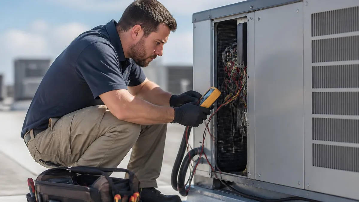
Crossing the R power wire with the C common wire creates a dead short across the transformer secondary. This will instantly blow the control fuse on the board, and on systems without a fuse it can burn out the transformer entirely. Always double-check these two terminals before restoring power, and replace a blown 3A or 5A fuse only after finding the underlying wiring fault.
Troubleshooting thermostat wiring problems becomes far less intimidating once you approach it methodically, starting with the simplest possibilities and working toward the complex. A blank thermostat screen most often points to a power issue: a dead battery, a tripped float switch on the condensate drain, a blown low-voltage fuse, or a missing common wire on a model that requires constant power. Begin by measuring voltage between R and C to confirm the transformer is delivering its expected 24 to 28 volts.
If the system will not heat, check that the W terminal is receiving a signal when the thermostat calls for heat. You can carefully jumper R to W at the thermostat base with power on to test whether the furnace responds; if it fires, the problem is likely in the thermostat or its configuration rather than the equipment. The same logic applies to cooling by jumpering R to Y, and to the fan by jumpering R to G, isolating exactly which circuit is failing.
Short cycling, where the system rapidly turns on and off, can stem from wiring issues such as a loose connection, a power-stealing thermostat without a true common, or anticipator settings on older mechanical units. Intermittent connections are notorious because they work during a quick test and fail under real operation. Gently tug each landed conductor and re-torque the terminal screws, since a wire that merely touches its terminal will create maddening intermittent faults.
When cooling and heating are reversed on a heat pump, the culprit is almost always the reversing valve configuration in the thermostat's installer settings or an O and B wire landed incorrectly. Confirm which terminal your equipment uses for the reversing valve, then set the thermostat's O/B preference to match. This adjustment is a software setting on modern thermostats, so no rewiring may be needed once you identify the correct orientation.
A frequently overlooked cause of mysterious failures is the condensate overflow safety switch. When the drain pan fills, this switch opens the 24V circuit to shut down cooling and prevent water damage, which can mimic a thermostat or wiring fault. Before chasing wiring ghosts, verify the float switch is closed and the drain is clear, because this simple component interrupts the same low-voltage circuit your thermostat depends on.
Documentation and patience win the day in troubleshooting. Keep the photo you took of the original wiring, reference the equipment's wiring diagram printed inside the cabinet door, and write down each voltage reading as you go. If you reach a point where the equipment itself appears faulty rather than the wiring, it may be time to consult qualified HVAC technicians near me who carry the diagnostic tools and experience to safely test line-voltage components and control boards.
With practice, the patterns become predictable. Most thermostat wiring complaints trace back to a small handful of root causes: missing common wires, loose terminals, blown fuses, tripped safety switches, and incorrect configuration settings. Master those five categories and you will resolve the overwhelming majority of service calls quickly, leaving only the genuinely complex equipment failures for deeper diagnosis.
Putting your thermostat wiring knowledge into practice starts with assembling the right tools and adopting habits that professionals rely on every day. A basic kit includes a quality multimeter for measuring AC voltage, a non-contact voltage tester for safety verification, a small flathead screwdriver for terminal screws, wire strippers sized for 18-gauge conductors, and electrical tape or wire labels. A smartphone camera is arguably the most valuable tool of all, since a clear photo of the original wiring is your safety net.
Develop the discipline of working from the equipment outward. Before you ever touch the thermostat, open the furnace or air handler, locate the control board, and study the terminal block and the wiring diagram printed inside the cabinet. This grounds your understanding in what the equipment actually expects, rather than assuming the thermostat end tells the whole story. Many confusing situations resolve instantly once you see how the wires land at the board.
When you strip and land conductors, leave just enough copper exposed to fully seat under the terminal screw without bare wire protruding to touch neighbors. Over-stripping invites shorts, while under-stripping leaves insulation under the screw and creates a poor connection. Tug-test every wire after tightening, because a connection that looks secure can still be loose enough to cause intermittent faults that are extremely tedious to diagnose later.
Take advantage of the installer setup menus on modern thermostats. These menus let you declare your equipment type, the number of heating and cooling stages, the heat pump reversing valve orientation, and whether auxiliary heat is electric or fossil fuel. Skipping this configuration is a common reason a correctly wired thermostat still misbehaves. The wiring delivers the signals, but the configuration tells the thermostat how to use them intelligently.
For anyone preparing for certification exams or building a career in the trade, thermostat wiring is a high-value topic because it ties together electrical theory, equipment operation, and customer-facing service skills. Practice reading diagrams from multiple manufacturers, since each presents the same information in slightly different layouts. The more diagrams you study, the faster you will recognize the universal patterns underneath the brand-specific styling.
It also pays to understand the business context around these skills, because thermostat upgrades are frequently the entry point to larger conversations about comfort and efficiency. Professionals who understand HVAC sales know that a simple thermostat service call can reveal opportunities to improve a customer's entire system, and explaining wiring clearly builds the trust that turns a one-time visit into a long-term relationship.
Finally, never stop verifying. Even seasoned technicians confirm voltage readings, double-check the R and C terminals, and test all modes before packing up. The cost of a few extra minutes of verification is trivial compared to the cost of a callback, a damaged control board, or a customer left without heat overnight. Methodical habits, not speed, define the technicians whose work consistently holds up over time.
HVAC Questions and Answers
HVAC Sales: The Complete Guide to Selling Heating and Cooling Systems, Building Customer Trust, and Closing More Deals
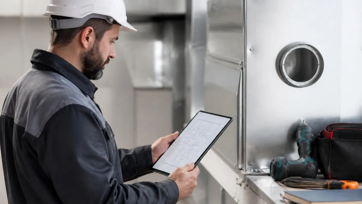
HVAC Technicians Near Me: The Complete Homeowner's Guide to Finding, Vetting, and Hiring Local Heating and Cooling Pros
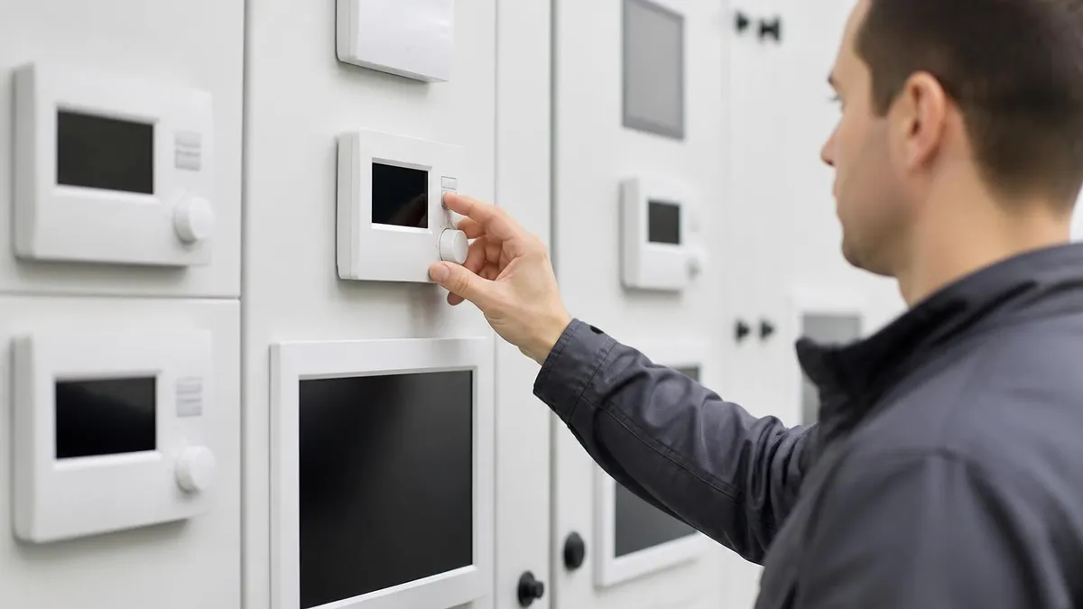
HVAC Air Duct Sealing: The Complete Homeowner and Contractor Guide to Sealing Ductwork for Efficiency, Comfort, and Indoor Air Quality

HVAC Replacement Services: Complete Guide to System Replacement, Costs, and What to Expect
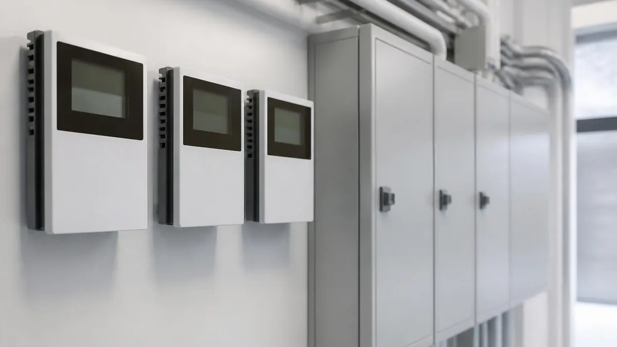
HVAC Solutions: The Complete Guide to Heating, Cooling, and Indoor Air Quality Systems for Homes and Buildings
About the Author

NATE Certified HVAC Technician & Licensing Exam Trainer
Universal Technical InstituteMike Johnson is a NATE-certified HVAC technician and EPA 608 universal-certified refrigerant handler with a Bachelor of Science in HVAC/R Technology. He has 19 years of commercial and residential HVAC installation and service experience and specializes in preparing technicians for NATE certification, EPA 608, A2L refrigerant safety, and state HVAC contractor licensing examinations.