MRI Equipment: A Complete Guide to Scanners, Coils, and Components 2026 July
Complete guide to MRI equipment — 📝 scanners, magnets, gradient coils, RF systems, and accessories. Learn how each component works and what techs need
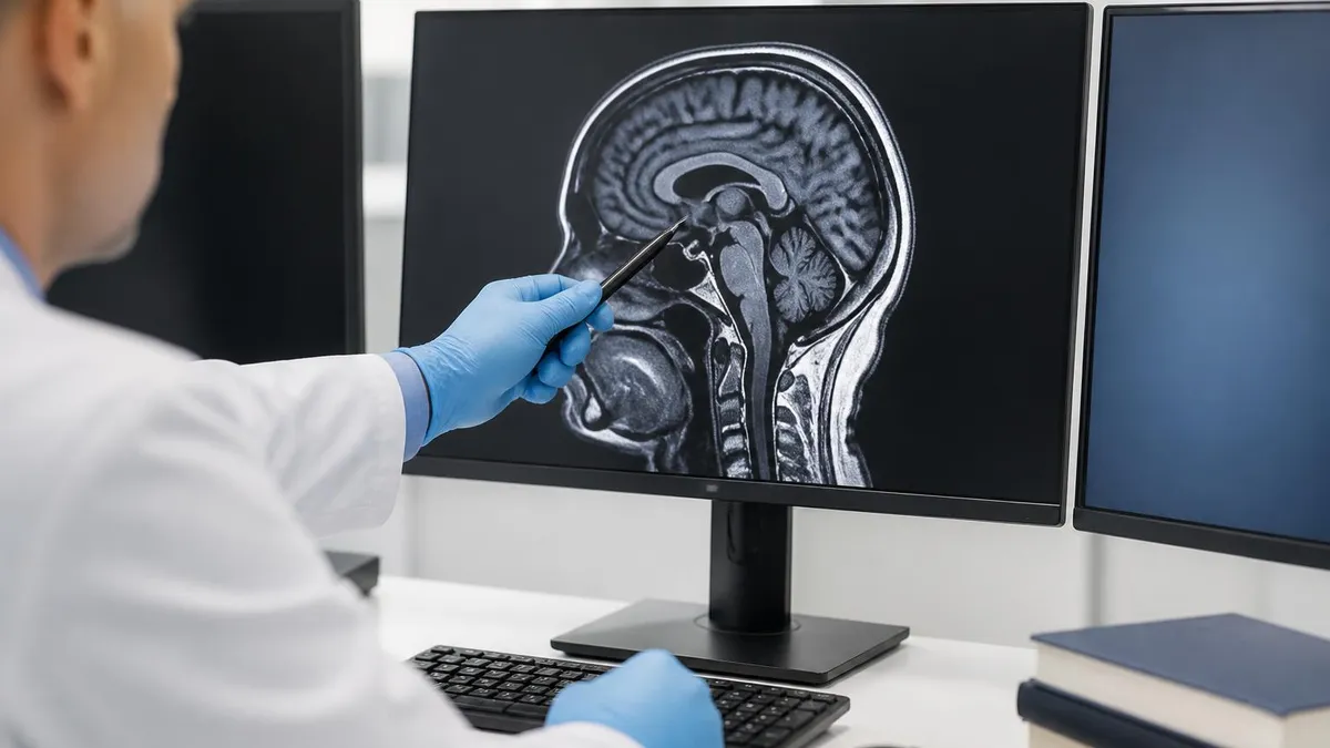
Modern mri equipment represents one of the most sophisticated convergences of physics, engineering, and clinical medicine ever assembled into a single diagnostic system. A typical scanner room contains a superconducting magnet cooled to roughly 4 Kelvin with liquid helium, gradient coils capable of switching magnetic fields thousands of times per second, radiofrequency transmitters and receivers tuned to the Larmor frequency, and a computing system that reconstructs raw k-space data into the anatomical images radiologists interpret every day in hospitals across the country.
For technologists, students preparing for the ARRT MRI registry, and anyone curious about how these machines actually work, understanding the major equipment categories is essential. Each component — the main magnet, the gradient subsystem, the RF chain, the patient table, the coil inventory, the cryogen plumbing, and the room shielding — plays a distinct role in producing diagnostic images. A failure or miscalibration in any one of them can degrade signal-to-noise ratio, introduce artifacts, or even compromise patient safety.
This guide walks through every major piece of mri equipment found in a clinical suite, from the multi-ton magnet at the heart of the scanner to the small surface coils placed directly on a patient's knee or wrist. We will cover field strengths from 0.3T open systems to 7T research platforms, the differences between active and passive shimming, how gradient performance affects sequence design, and why RF coils come in dozens of shapes for different anatomy.
Along the way, we'll connect equipment specifications to the clinical decisions technologists make every shift. Knowing why a 3T scanner produces sharper images than a 1.5T system but also amplifies certain artifacts helps you select sequences intelligently. Understanding the duty cycle of your gradients explains why some protocols cannot be shortened indefinitely. Recognizing the cost of a helium quench reinforces why magnet room safety protocols are non-negotiable.
The economic picture matters too. A new wide-bore 3T scanner can cost between $1.5 million and $3 million, with annual service contracts running $150,000 or more. Cryogen refills, coil repairs, and quench pipe inspections add ongoing operational expense. Understanding the history of MRI helps contextualize how today's equipment evolved from refrigerator-sized resistive magnets in the late 1970s into the high-field, multi-channel systems now standard in tertiary care centers.
Whether you are a registry candidate memorizing equipment specifications, a clinical technologist troubleshooting an artifact, a biomedical engineer evaluating a service contract, or a facility planner sizing an installation, this guide provides a structured tour of every major MRI hardware component. We'll cover specifications, clinical implications, safety considerations, and the practical knowledge needed to work confidently in any MRI environment.
By the end, you should be able to look at any clinical or research scanner and identify its major subsystems, understand approximately what each costs and how often it requires service, and explain how the entire chain — from cryogen vessel to reconstruction computer — collaborates to produce a single diagnostic image. That foundational equipment knowledge underlies safe scanning, accurate sequence selection, and informed conversations with vendors, physicists, and service engineers.
MRI Equipment by the Numbers
Core MRI Equipment Components
The superconducting magnet generates the static B0 field, ranging from 0.3T to 7T. It is cooled with liquid helium and provides the foundation for nuclear magnetic resonance signal generation.
Three orthogonal coils produce linear variations in the magnetic field along X, Y, and Z axes. They enable spatial encoding, slice selection, and create the loud knocking sounds during scans.
A body coil and amplifier deliver radiofrequency pulses at the Larmor frequency, tipping proton magnetization away from B0 to produce a detectable transverse signal for imaging.
Surface and phased-array coils placed close to anatomy capture the weak MR signal. Multi-channel coils improve signal-to-noise ratio and enable parallel imaging acceleration.
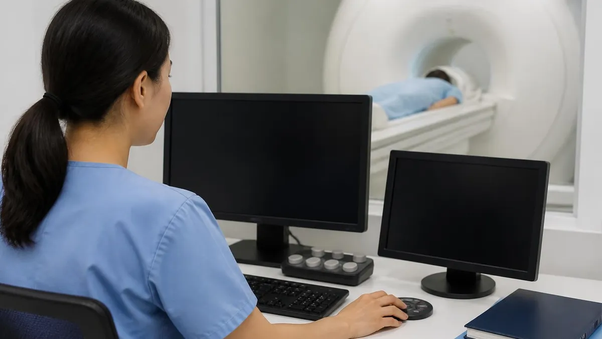
Powerful reconstruction computers perform Fourier transforms on raw k-space data, while the operator console controls sequence parameters, patient information, and image archiving workflows.
The main magnet is the single most expensive and consequential piece of mri equipment in any scanner. Clinical systems overwhelmingly use superconducting magnets built from niobium-titanium wire wound into solenoidal coils and immersed in a bath of liquid helium at approximately 4 Kelvin. Once energized — a process called ramping — the magnet sustains its field indefinitely with essentially zero resistance and zero power draw, which is why a scanner can sit powered down overnight and still pose a strong magnetic hazard to anyone entering the room.
Field strength directly affects image quality and clinical capability. A 1.5T scanner remains the workhorse for general radiology because it balances signal, artifact behavior, and patient comfort across a wide variety of exams. A 3T system roughly doubles the available signal, enabling thinner slices, higher matrix sizes, and faster functional and spectroscopy techniques. However, 3T also doubles chemical shift, increases susceptibility artifacts, raises specific absorption rate, and amplifies dielectric effects, particularly in larger patients.
Bore diameter matters as much as field strength for patient throughput. Traditional 60-centimeter bores can be challenging for claustrophobic, obese, or pediatric patients, while modern 70-centimeter wide-bore systems substantially reduce scan cancellations. Open MRI scanners using permanent or resistive magnets sacrifice field strength — typically 0.3T to 1.2T — in exchange for true open architecture, which is invaluable for severely claustrophobic patients or imaging weight-bearing joints.
Shimming is the process of correcting field inhomogeneity caused by the magnet itself and by every patient who enters the bore. Passive shimming uses small iron pieces placed inside the cryostat during installation. Active shimming uses additional superconducting coils and dynamic room-temperature shim currents adjusted at the start of every exam. Poor shimming produces fat-saturation failures, geometric distortion, and broadened spectroscopy peaks. The MRI medical abbreviation glossary explains many shim-related terms registry candidates frequently encounter.
Gradient subsystems sit just inside the magnet bore and consist of three orthogonal coil sets driven by powerful amplifiers. Modern clinical gradients deliver amplitudes of 40 to 80 millitesla per meter and slew rates of 150 to 200 tesla per meter per second. These specifications determine the minimum echo spacing achievable in echo-planar imaging, the maximum b-value usable in diffusion, and the spatial resolution available in time-resolved angiography.
Gradient performance is constrained by peripheral nerve stimulation thresholds set by IEC and FDA standards. Pushing slew rates higher would shorten EPI readouts further but risks causing the patient to perceive muscle twitches, which is uncomfortable and potentially unsafe. Engineers also must manage gradient heating, acoustic noise — which routinely exceeds 100 decibels — and the substantial Lorentz forces that cause coils to vibrate violently during rapid switching.
The RF chain includes a transmit amplifier capable of delivering tens of kilowatts of peak power, the body coil integrated into the magnet bore, and a network of preamplifiers and digitizers connected to whichever receive coil is in use. RF interference from outside the scan room would obliterate the weak MR signal, which is why every magnet room sits inside a copper or aluminum Faraday cage and uses penetration panels and waveguides for all power and data connections.
MRI Practice Test Questions
Prepare for the MRI - Magnetic Resonance Imaging exam with our free practice test modules. Each quiz covers key topics to help you pass on your first try.
MRI Knowledge
MRI Exam Questions covering Knowledge. Master MRI Test concepts for certification prep.
MRI Physics
Free MRI Practice Test featuring Physics. Improve your MRI Exam score with mock test prep.
MRI Anatomy and Pathology
MRI Test Prep for MRI Anatomy and Pathology. Practice MRI Quiz questions and boost your score.
MRI Anatomy and Positioning
MRI Questions and Answers on MRI Anatomy and Positioning. Free MRI practice for exam readiness.
MRI Contrast Agents
Free MRI Quiz on MRI Contrast Agents. MRI Exam prep questions with detailed explanations.
MRI Patient Care and Positioning
MRI Practice Questions for MRI Patient Care and Positioning. Build confidence for your MRI certification exam.
RF Coils and MRI Equipment Categories
Volume coils completely surround the anatomy of interest and provide uniform RF transmission and reception across the imaging volume. The integrated body coil within the scanner bore is the largest volume coil and is used as the default transmitter for most clinical exams, while head coils, knee coils, and extremity coils are smaller volume designs optimized for specific anatomical regions.
These coils excel at homogeneity and are preferred when uniform signal across a large field of view matters more than peak sensitivity. The classic birdcage geometry, introduced in the 1980s, remains foundational. Modern head coils integrate volume transmission with multi-channel receive arrays, combining the homogeneity of a birdcage with the SNR and parallel imaging benefits of phased-array reception.
High-Field vs Low-Field MRI Equipment
- +Higher field strength produces greater signal-to-noise ratio for sharper images
- +Enables advanced techniques like fMRI, spectroscopy, and high-resolution diffusion
- +Supports thinner slices and larger matrices in clinically acceptable scan times
- +Better fat suppression and improved contrast for many neuro and musculoskeletal exams
- +Faster parallel imaging acceleration with multi-channel coils
- +Stronger gradients pair well with high field for cutting-edge protocols
- −Increased susceptibility artifacts near metal implants and air-tissue interfaces
- −Higher specific absorption rate limits some sequences in larger patients
- −Greater chemical shift artifact requires wider receive bandwidths
- −Dielectric effects can produce shading and signal dropouts in abdomen and pelvis
- −Equipment cost, siting requirements, and helium consumption all rise with field strength
- −Acoustic noise and peripheral nerve stimulation concerns become more prominent
Daily MRI Equipment QC Checklist
- ✓Verify cryogen levels and confirm magnet field strength is on target
- ✓Inspect the quench vent pipe and confirm room oxygen monitor is functioning
- ✓Run the vendor-provided daily QA phantom and review SNR and uniformity results
- ✓Check all RF coils for cracked housings, frayed cables, and bent connector pins
- ✓Confirm patient call buzzer, ventilation, and intercom are operating correctly
- ✓Inspect the patient table for smooth motion and accurate position readout
- ✓Verify zone signage, ferrous detectors, and door interlocks are working
- ✓Confirm cryogen and chiller alarms communicate to the appropriate personnel
- ✓Check console computer for available storage and pending software updates
- ✓Document any artifacts or unusual noises in the daily QA log and notify service
Specifications drive sequence choices
Knowing your scanner's maximum gradient amplitude, slew rate, and RF channel count is not academic trivia — these specifications directly determine which protocols you can run, what minimum echo times you can achieve, and how aggressively you can accelerate parallel imaging without sacrificing diagnostic quality.
Safety equipment surrounding the magnet is just as critical as the imaging hardware itself. Every MRI suite is divided into four zones, with Zone IV being the scan room itself. Access to Zones III and IV must be restricted to MR personnel who have completed appropriate training, and the boundary between Zone II and Zone III must be physically controlled — typically with locked doors, key cards, or screened entry by an MR technologist.
Ferromagnetic detection systems mounted at the Zone III entrance provide an additional safeguard against projectile incidents. These systems detect ferrous objects on patients, visitors, or staff who may have inadvertently forgotten to remove keys, tools, oxygen cylinders, or medical equipment. While they do not replace a thorough screening interview, they have prevented numerous serious incidents and are considered a best-practice standard in modern installations.
The quench pipe is one of the most critical safety components in any superconducting MRI installation. If the magnet quenches — a sudden loss of superconductivity — the helium bath rapidly boils off and must be vented safely to the outside atmosphere. A blocked or compromised quench pipe could result in helium venting into the scan room, displacing oxygen and creating an asphyxiation hazard. Annual inspection of the entire vent path is mandatory.
Oxygen monitors in the scan room provide real-time warning of any cryogen leak. They should trigger audible and visual alarms at 19.5 percent oxygen concentration and initiate emergency ventilation. Door interlocks should prevent the room from being sealed in a low-oxygen condition. Staff must be trained to recognize the symptoms of mild asphyxia and evacuate immediately if alarms sound.
RF shielding integrity is verified during installation and re-tested periodically. Even a small gap in the Faraday cage — for example, a damaged door gasket or a corroded waveguide — can allow ambient RF interference into the room, producing zipper artifacts and other unwanted patterns on images. Service engineers use spectrum analyzers to verify shielding effectiveness, typically requiring at least 90 to 100 decibels of attenuation at the operating frequency.
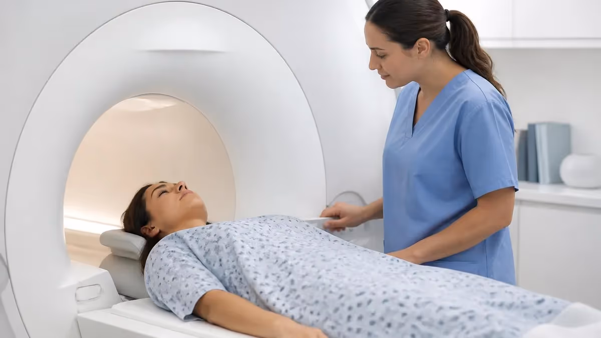
Patient-facing equipment includes the table, immobilization devices, hearing protection, and the squeeze ball or call button. Foam pads, straps, and head holders should be inspected daily for cleanliness and integrity. Hearing protection is mandatory for every patient and must be appropriate for the noise levels of the sequences being run — typically a combination of earplugs and headphones for any sequence exceeding 99 decibels. Resources on MRI with braces illustrate how patient screening and equipment interact for specific safety scenarios.
Emergency equipment includes the magnet stop button, which terminates RF and gradient activity but does not quench the magnet, and the rundown or emergency quench button, which is used only in true life-threatening situations such as a person pinned against the bore by a ferromagnetic object. Pressing the quench button intentionally destroys the magnet field and costs tens of thousands of dollars in helium, so its use must be appropriate to the emergency.
Liquid helium expands roughly 700 times in volume when it boils. A quench releasing thousands of liters of helium into a scan room with a blocked vent pipe will displace oxygen within seconds. Annual quench pipe inspection and functional oxygen monitoring are non-negotiable safety requirements at every MRI installation.
Maintenance economics shape every facility's MRI equipment strategy. A new scanner typically arrives with a one- to two-year warranty, after which the facility purchases a service contract from the OEM or a third-party provider. Full-service OEM contracts on a 3T system can run $150,000 to $250,000 per year and typically include parts, labor, software updates, helium refills, and guaranteed uptime. Third-party contracts cost less but may not cover proprietary software updates or certain high-cost parts.
Coil repair is one of the most common ongoing service expenses. Phased-array coils contain delicate preamplifiers, fragile cable assemblies, and many connector pins, all of which fail over time from repeated patient positioning. A dropped coil can cost $20,000 to $80,000 to replace. Many facilities now train technologists in basic coil handling protocols and use coil carts to minimize wear during routine workflow.
Helium consumption depends on magnet design. Older magnets with conventional cryocoolers may boil off measurable helium each month, while modern zero-boil-off systems use closed-cycle refrigeration to maintain bath levels indefinitely under normal operation. Even zero-boil-off systems require helium top-offs after planned service events or unplanned cryocooler failures. Global helium supply volatility has made cryogen budgeting a meaningful concern for many imaging centers.
Software upgrades roll out every one to two years and frequently introduce new sequences, accelerated reconstructions, and AI-assisted workflow tools. Deep-learning denoising, automated landmarking, and intelligent slice planning can meaningfully improve throughput and image quality on existing hardware, which is part of why software is often a differentiator in vendor selection rather than just hardware specifications.
Planned downtime for preventive maintenance typically runs 16 to 24 hours every six to twelve months. During these visits, service engineers verify magnet homogeneity, check gradient amplifier output, calibrate RF coils, inspect cryogen plumbing, and apply software patches. Scheduling these visits during weekends or evenings minimizes the impact on clinical operations, especially in high-volume centers running extended hours.
End-of-life planning matters too. Most clinical scanners operate productively for 10 to 15 years before image quality, sequence library, and reliability fall behind contemporary standards. Decommissioning a superconducting magnet requires a controlled ramp-down, helium recovery, and careful removal — a process that can take several days and requires specialized contractors. Articles on MRI with and without contrast illustrate how new contrast protocols and sequences often drive upgrade decisions.
Finally, biomedical engineering teams play an essential role in equipment management. They coordinate service visits, maintain QA records, track downtime metrics, and serve as the technical liaison between clinical staff and vendor engineers. A strong relationship between MRI technologists and biomed staff dramatically improves response times when equipment problems arise and helps ensure that minor issues are addressed before they cause clinical disruptions.
For technologists working with mri equipment daily, a handful of practical habits separate confident operators from anxious ones. Always verify the correct receive coil is connected and recognized by the system before patient setup — running a sequence on the body coil when a dedicated array was intended produces noticeably worse images and wastes valuable scan time. Develop a routine of glancing at the coil status indicator on the console at the start of every exam.
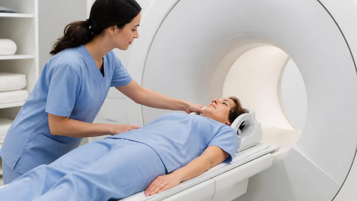
Patient positioning is equipment-dependent. Each coil has an isocenter mark or laser landmarking guide, and positioning the anatomy of interest precisely at magnet isocenter optimizes both shim quality and gradient linearity. Off-isocenter scanning produces geometric distortion, fat-saturation failure, and reduced signal — all of which can be mistaken for pathology or technique errors when the underlying cause is simply poor landmarking.
Acoustic noise management deserves attention beyond just handing patients earplugs. Confirm headphones are properly seated, music or comfort audio is audible at appropriate levels, and the patient understands they can squeeze the call ball at any time. Some advanced systems offer quiet sequences using specialized gradient waveforms that reduce noise by 10 to 30 decibels — using these for sensitive patients can dramatically improve compliance and image quality.
Artifact recognition often points directly to equipment issues. Zipper artifacts running across the phase encoding direction usually indicate RF leakage from a damaged door seal or external interference. Discrete bright spots may signal a failing gradient amplifier or bad coil element. Asymmetric ghosting can reveal table position errors. Documenting and reporting artifacts to service quickly prevents small problems from becoming major outages.
Stay current with vendor application training. Major MRI manufacturers release new sequences, reconstruction algorithms, and workflow tools through software updates, and application specialists can provide on-site or virtual training that dramatically improves how effectively your team uses the equipment. Many sites underutilize their scanners simply because no one was trained on the new accelerated diffusion or AI-assisted protocols included in last year's upgrade.
Build a working relationship with your service engineer. Knowing their direct phone number, understanding their typical response time, and being able to describe symptoms precisely — including sequence parameters, coil used, and exact error codes — accelerates every service call. The more accurately you can describe a problem, the more likely a remote diagnosis will resolve it without an on-site visit. Reviewing common MRI findings also helps technologists differentiate true pathology from equipment artifacts during scan QA.
Finally, never become complacent about safety. The magnet is always on, even when the console is dark and the lights are off. Project screening every person every time, follow ferrous detection alerts seriously, secure all loose items before entering Zone IV, and respect the cryogen system. The most catastrophic MRI incidents on record have almost always involved a moment when a trained professional made an exception to a safety rule they otherwise knew well.
MRI Questions and Answers
About the Author
Medical Laboratory Scientist & Clinical Certification Expert
Johns Hopkins UniversityDr. Sandra Kim holds a PhD in Clinical Laboratory Science from Johns Hopkins University and is certified as a Medical Technologist (MT) and Medical Laboratory Scientist (MLS) through ASCP. With 16 years of clinical laboratory experience spanning hematology, microbiology, and molecular diagnostics, she prepares candidates for ASCP board exams, MLT, MLS, and specialist certification tests.
Join the Discussion
Connect with other students preparing for this exam. Share tips, ask questions, and get advice from people who have been there.
View discussion (6 replies)