
Non-Destructive Testing Tools: Complete Guide to NDT Equipment and Methods
Master non destructive testing tools — equipment types, methods, and real-world applications. Your complete 2026 September NDT guide. ✅

Non destructive testing tools are the backbone of modern industrial inspection, allowing engineers and technicians to evaluate materials, components, and structures without causing any damage to the tested item. From aerospace turbine blades to underground pipelines, these instruments provide critical insights into material integrity that would otherwise require cutting, breaking, or destroying the specimen. Understanding the full range of available equipment is essential for anyone entering or advancing within the NDT field, and for organizations that depend on reliable safety inspections.
The variety of non-destructive testing tools available today is extraordinary. Decades of research and technological advancement have produced instruments capable of detecting microscopic surface cracks, sub-surface voids, corrosion hidden beneath coatings, and even structural flaws invisible to the naked eye. Each method uses a different physical principle — sound waves, magnetic fields, X-ray radiation, electrical currents, or liquid penetrants — to reveal defects that could compromise structural performance or safety under load or pressure.
Selecting the right tool for a given application is both a science and a skill. An ultrasonic thickness gauge may be ideal for measuring wall thinning in a corroded pipe, while magnetic particle testing equipment is better suited to detecting surface and near-surface cracks in ferromagnetic steel welds. Eddy current probes excel at detecting small fatigue cracks in aluminum aircraft skins, and radiographic equipment can reveal internal casting defects that no surface technique would ever find. Matching the inspection tool to the defect type and material is a fundamental competency for certified NDT professionals.
The NDT industry in the United States is governed by a combination of national standards, industry specifications, and certification requirements. Organizations like ASNT (American Society for Nondestructive Testing) and AWS (American Welding Society) publish recommended practices and qualification schemes that define what equipment must be used, how it must be calibrated, and what documentation is required. Technicians who understand both the tools and the underlying standards are far more valuable in the workforce and command higher salaries as a result.
For students and early-career technicians preparing for certification exams, mastering the operational principles of common NDT tools is absolutely essential. Exam questions routinely cover equipment setup, calibration procedures, sensitivity requirements, and the interpretation of test indications. Whether you are preparing for ASNT Level II certification or working toward an employer-specific qualification, a deep understanding of how each instrument works — and what it can and cannot detect — will directly improve your exam scores and your on-the-job performance.
This comprehensive guide covers every major category of non-destructive testing tools currently in use across US industries. We explore the equipment used in ultrasonic, magnetic particle, liquid penetrant, radiographic, eddy current, and visual testing methods. We also examine emerging digital and automated inspection technologies that are reshaping the field. If you want to get hands-on practice before your next certification exam, exploring resources focused on non destructive testing tools training will accelerate your preparation considerably.
Whether you are a student just learning the basics, an experienced technician seeking to expand your method knowledge, or a quality engineer evaluating inspection options for your facility, this guide will give you a thorough, practical understanding of the tools that keep America's infrastructure, manufacturing, and energy systems safe and reliable.
NDT Tools & Industry by the Numbers

Major Categories of NDT Tools
Pulser-receivers, transducers, thickness gauges, and phased array systems use high-frequency sound waves to detect internal flaws and measure wall thickness in metals, composites, and plastics. Industry standard for weld and pipe inspection.
Yokes, coils, prod sets, and bench units create magnetic fields that cause ferromagnetic particles to gather at surface and near-surface discontinuities in steel and iron components. Fast, sensitive, and cost-effective for weld inspection.
Penetrant sprays, developers, black lights, and cleaning supplies reveal surface-breaking defects in virtually any non-porous material. Ideal for detecting cracks, porosity, and seams in castings, forgings, and welds.
X-ray machines, gamma-ray sources, film processors, and digital detector arrays produce images of internal structures, revealing voids, inclusions, and weld root defects invisible to surface methods.
Eddy current probes, impedance analyzers, and array scanners use electromagnetic induction to detect surface and near-surface cracks, corrosion, and conductivity variations in conductive materials without contact.
Ultrasonic testing equipment represents one of the most versatile and widely deployed categories of NDT tools in the United States. A standard UT inspection system consists of a pulser-receiver unit, one or more transducers (also called probes or search units), coaxial cables, and calibration reference standards. The pulser-receiver generates a high-frequency electrical pulse that the transducer converts into sound energy. When that sound wave travels through a material and encounters a discontinuity or the back wall, it reflects back to the transducer and is displayed on an A-scan screen as an amplitude peak at a specific time-of-flight position.
Conventional UT equipment has evolved significantly over the past two decades. Analog flaw detectors have largely been replaced by digital instruments with color displays, data logging, and computer connectivity. Portable units like those from Olympus, GE Inspection Technologies, and Sonatest are common on job sites across the oil and gas, power generation, and aerospace industries. Thickness gauges — a specialized subset of UT equipment — are designed specifically for single-sided access measurement, making them invaluable for corrosion monitoring where the opposite side of a pipe or vessel wall is inaccessible.
Phased array ultrasonic testing (PAUT) takes conventional UT to a higher level by using a multi-element transducer array that can electronically steer and focus the sound beam without physically moving the probe. This allows a single scan to cover a large volume of material and produce detailed cross-sectional images called S-scans. PAUT is now routinely specified in ASME and AWS codes for weld inspection, and operators certified in PAUT command premium salaries. The associated equipment — phased array instruments, encoded scanners, and analysis software — represents a substantial capital investment but dramatically speeds up inspection throughput.
Eddy current testing tools operate on a completely different physical principle but share the same goal: detecting hidden flaws without destructive means. An eddy current probe induces alternating electromagnetic fields into a conductive material. Any change in conductivity, permeability, or geometry — such as a crack or corrosion pit — alters the eddy current flow pattern and produces a measurable impedance change in the probe coil. This impedance change is displayed on an impedance plane or as a time-base signal, allowing trained operators to characterize and size indications with remarkable precision.
Eddy current array (ECA) technology extends the capability of conventional ET probes by using multiple coil elements arranged in a grid pattern. Like phased array UT, ECA can cover large surface areas quickly and produce C-scan images that make reporting and documentation far more straightforward. ECA equipment is widely used in aerospace for inspecting fastener holes, lap joints, and wing skins, and is increasingly used in oil and gas for heat exchanger tube inspection. The combination of speed and sensitivity makes ECA a preferred choice wherever large surface areas must be inspected for fatigue cracks.
Magnetic particle testing equipment is prized for its simplicity, speed, and sensitivity to surface-breaking and near-surface discontinuities in ferromagnetic materials. The most common portable MT tool is the magnetic yoke — a horseshoe-shaped electromagnet or permanent magnet that creates a longitudinal magnetic field between its poles.
When placed on a steel weld, the yoke magnetizes the surrounding area, and any surface crack perpendicular to the field lines will cause magnetic flux to leak, attracting dry or wet fluorescent iron particles that form a visible indication. Portable AC and DC yokes are inexpensive, require minimal maintenance, and are specified in countless AWS D1.1 and API 1104 inspection procedures.
For larger or more complex components, stationary magnetic particle benches provide both circular and longitudinal magnetization using head shots, coil shots, and prod techniques. These bench units are common in manufacturing facilities that produce high volumes of castings, forgings, and machined parts. Wet fluorescent magnetic particle systems use a bath of iron oxide particles suspended in oil or water that is sprayed or flowed over the magnetized part, then examined under ultraviolet (black) light.
The fluorescent contrast dramatically improves the visibility of fine cracks and is preferred when detection sensitivity is paramount. Understanding when to use wet versus dry particles, and which magnetization technique to apply, is a core competency tested on every ASNT Level II MT certification exam.
Comparing NDT Methods: Tools, Applications, and Limitations
Liquid penetrant testing tools are among the most accessible and affordable in the entire NDT toolkit. A basic PT kit includes penetrant, cleaner/remover, and developer — available in aerosol cans for field use or bulk containers for production lines. The method works on any non-porous material, making it the go-to choice for aluminum, stainless steel, titanium, ceramics, and plastics where magnetic particle testing is not applicable. Fluorescent PT systems, examined under 365 nm UV light, offer exceptional sensitivity for fine cracks in aerospace components.
Magnetic particle testing excels specifically on ferromagnetic materials — carbon steel, low-alloy steel, and certain grades of stainless steel. The tools are simple: a yoke, particles, and adequate lighting or a UV lamp for fluorescent systems. MT detects not just surface cracks but also near-surface discontinuities up to about 1/4 inch deep, giving it an advantage over PT for subsurface flaws. Production facilities often invest in stationary MT benches with automated particle application and UV illumination systems to maximize throughput and inspector consistency.

NDT Tools: Advantages and Limitations You Need to Know
- +Test components remain fully intact and in service after inspection, eliminating costly downtime
- +Wide range of tools available to match virtually any material, geometry, or defect type
- +Real-time results from portable instruments enable rapid go/no-go decisions in the field
- +Digital data acquisition allows permanent documentation and trend analysis over time
- +Many NDT methods can be automated or semi-automated for high-volume production inspection
- +Non-ionizing methods (UT, MT, PT, ET) require no radiation safety controls or special permits
- −Equipment calibration requirements add cost and complexity to every inspection procedure
- −Operator skill and certification level significantly affect the reliability of results
- −Radiographic testing equipment requires strict radiation safety protocols, licensing, and controlled access areas
- −No single NDT tool can detect all defect types — multiple methods may be needed for comprehensive inspection
- −False indications (non-relevant indications) can result in unnecessary part rejection if operators are not well trained
- −Phased array UT and eddy current array equipment represents significant capital investment
Pre-Inspection Checklist: Setting Up NDT Tools Correctly
- ✓Verify that all equipment calibration records are current and within the required calibration interval.
- ✓Confirm the correct NDT method and tool type are specified in the applicable inspection procedure.
- ✓Inspect cables, probes, and connectors for damage before connecting to the instrument.
- ✓Perform an instrument performance check using the appropriate reference standard for the method.
- ✓Document equipment serial numbers, calibration dates, and instrument settings on the inspection record.
- ✓Confirm that the surface condition of the test piece meets cleanliness requirements for the chosen method.
- ✓Verify that lighting levels (white light for VT/PT, UV intensity for fluorescent methods) meet code minimums.
- ✓Establish and verify scanning sensitivity by performing a calibration on a reference block or notch standard.
- ✓Confirm that all consumables (penetrant, developer, particles, couplant) are within their expiration dates.
- ✓Ensure the inspector holds the required certification level for the method and product form being inspected.
Calibration Is Not Optional — It Is the Foundation of Valid Results
Every NDT instrument must be calibrated to a known reference standard before and during inspection. ASME, AWS, and API codes all specify calibration block requirements, sensitivity settings, and verification intervals. An uncalibrated instrument may detect some defects while missing others entirely, creating a false sense of security. Always document your calibration data — it is your legal and technical defense if a weld or component later fails in service.
Calibration is the process of adjusting an NDT instrument's sensitivity and response so that its indications accurately represent real conditions in the material being tested. For ultrasonic testing, calibration typically involves using a reference block — such as an IIW (International Institute of Welding) block or an ASTM E428 reference block — to set the distance-amplitude correction (DAC) curve or transfer sensitivity. This calibration ensures that a reflector of a given size at a given depth produces a consistent, repeatable screen height, allowing the operator to compare production test results against a known baseline.
For magnetic particle testing, calibration involves verifying the strength and direction of the magnetic field using a Hall-effect Gaussmeter or a pie gauge. ASTM E709 requires that field strength fall within specified limits (generally 30 to 60 Gauss tangential field strength at the surface) to ensure adequate magnetization for defect detection.
UV light intensity must also be measured with a calibrated photometer to confirm that the black light intensity at the part surface meets the 1,000 µW/cm² minimum specified in most procedures. These equipment verification steps are not bureaucratic formalities — they are the quantitative evidence that the inspection was performed correctly.
Liquid penetrant testing calibration is somewhat simpler in concept but equally important in practice. Penetrant systems are qualified by testing them against a known cracked panel, such as a titanium or chrome-plated cracked panel, to verify that the system can reliably reveal cracks of a specified size. The penetrant dwell time, developer application method, and development time must all be verified and documented for each inspection. Temperature also plays a critical role — most PT procedures specify a surface temperature range of 40°F to 125°F, and inspections performed outside this range require special procedure qualification.
Radiographic testing calibration involves verifying source-to-film distance, exposure time, film density, and image quality indicator (IQI) visibility. IQIs — sometimes called penetrameters — are small devices made of the same material as the test piece, placed in the radiation beam to verify that the radiograph has adequate contrast and resolution to detect the minimum required defect size.
Wire-type IQIs (per ASTM E747) and hole-type IQIs (per ASTM E1025) are the two most common types used in US industry. Digital radiography systems require additional qualification steps to verify detector uniformity, dynamic range, and spatial resolution according to ASTM E2698 or similar standards.
Eddy current calibration requires setting the instrument's phase angle, gain, and frequency to produce a consistent response from known reference notches or holes in a calibration standard. The calibration standard is typically made from the same alloy and temper as the test piece and contains reference defects of specified size — for example, electrical discharge machined (EDM) notches of 0.010 inch depth for surface crack detection in aluminum. Because eddy current response is sensitive to liftoff (the gap between the probe and the surface), calibration must also account for any surface coatings or irregularities present during production inspection.
Documentation standards for NDT equipment calibration are specified by both the applicable industry code and the employer's written practice. ASNT SNT-TC-1A and CP-189 require that employers maintain records of technician qualifications, but they also implicitly require that the tools those technicians use be demonstrably fit for purpose. ISO 9712 — the international standard for NDT personnel certification — similarly requires that inspection procedures reference specific equipment requirements. A well-documented calibration record is not just good practice; it is a contractual and legal requirement in regulated industries like nuclear power, aerospace, and pressure vessel fabrication.
For technicians preparing for Level II certification exams, the calibration topics covered in this section appear frequently in written and practical examinations. Understanding the purpose of each calibration step, the acceptance criteria, and the consequences of performing an inspection with an improperly calibrated instrument is fundamental knowledge that every certified NDT professional must possess. Practice exam questions on calibration are among the highest-yield study topics across all NDT methods.

Industrial radiographic testing equipment — including X-ray machines and gamma-ray sources — is regulated by the US Nuclear Regulatory Commission (NRC) and state radiation control programs. Operating this equipment without a valid radiographer's license and appropriate radiation safety officer oversight is illegal and potentially dangerous. Always confirm your employer holds a valid radiographic materials license and that all RT personnel are properly trained and monitored with dosimetry badges.
The landscape of non-destructive testing tools is changing rapidly as digital technology, artificial intelligence, and robotics intersect with traditional inspection science. Phased array ultrasonic testing (PAUT) has already become mainstream, but total focusing method (TFM) — also called full matrix capture (FMC) — represents the next frontier. TFM collects full waveform data from every transmitter-receiver combination in a phased array probe and uses computational algorithms to reconstruct a focused image of the entire inspection volume simultaneously. The result is dramatically improved defect sizing accuracy and the ability to detect and characterize defects that conventional PAUT would struggle to resolve.
Automated ultrasonic testing (AUT) systems use encoded scanners, computer-controlled probe positioning, and real-time data acquisition to perform reproducible, high-speed inspections of welds, composites, and corrosion-sensitive structures. In the pipeline industry, AUT systems are routinely used for girth weld inspection using zone discrimination technique, where the weld cross-section is divided into multiple height zones and each zone is assigned a dedicated UT beam. This produces a permanent, reviewer-ready dataset that can be re-analyzed digitally without re-performing the physical inspection — a significant advantage for dispute resolution and quality audits.
Guided wave testing (GWT) is an ultrasonic technique that uses low-frequency, long-range sound waves to screen large lengths of pipe from a single test point. A ring of transducers clamped around a pipe can generate guided waves that propagate hundreds of feet in both directions, reflecting from changes in cross-sectional area caused by corrosion or mechanical damage.
GWT does not provide the precision sizing capability of conventional UT, but it is extraordinarily efficient for prioritizing which sections of a long pipeline require more detailed follow-up inspection. This makes it indispensable for pipelines buried underground or insulated with jacketing that would be prohibitively expensive to remove for conventional inspection.
Infrared thermography (IRT) is a non-contact NDT method that uses thermal imaging cameras to detect temperature variations on or near the surface of a component. Passive thermography relies on natural temperature differences to reveal delaminations in composites, moisture ingress in building envelopes, or electrical hot spots in switchgear.
Active thermography uses external heat sources — flash lamps, induction heaters, or ultrasonic energy — to introduce a controlled thermal pulse, then monitors the temperature decay pattern to detect subsurface defects. IRT is increasingly used in the wind energy sector for blade inspection, in aerospace for composite fuselage panel inspection, and in the construction industry for building envelope surveys.
Acoustic emission testing (AET) is a passive monitoring technique that detects the stress waves generated when a material deforms, cracks, or leaks. Rather than scanning a component with an external energy source like UT or RT, AET sensors are attached to the structure and listen for acoustic events that occur as the structure is loaded or pressurized during operation or a controlled proof test.
AET is used to monitor pressure vessels, storage tanks, bridges, and aircraft structures during service or testing, providing a continuous window into structural health rather than a periodic snapshot. The technique can detect active crack growth in real time — an important capability that no other NDT method can match.
Digital radiography and computed tomography (CT) are reshaping industrial radiographic inspection. Digital detector arrays replace traditional film with a reusable imaging panel that produces a digital image in seconds rather than the minutes required for film processing. Industrial CT scanners, long common in medical imaging, are now routinely used in aerospace and automotive manufacturing to create three-dimensional volumetric images of castings, additive manufacturing parts, and assemblies. CT reveals not just the presence but the exact three-dimensional shape, position, and size of internal features and defects, enabling dimensional metrology alongside defect detection in a single scan pass.
Drone-based inspection is one of the fastest-growing applications of visual testing technology. Remotely piloted aircraft equipped with high-resolution cameras, thermal sensors, and even ultrasonic contact probes are being deployed to inspect bridges, transmission towers, wind turbine blades, storage tanks, and elevated flare stacks — structures that previously required expensive scaffolding, rope access, or aerial lift equipment. The combination of drone mobility and advanced sensor payloads is dramatically reducing both inspection cost and inspector risk, and is opening new career paths for NDT professionals with combined expertise in aviation and inspection technology.
For technicians and students preparing for NDT certification examinations, a structured approach to studying NDT tools and equipment is far more effective than simply memorizing specifications. Start by building a thorough understanding of the physical principles underlying each method. You cannot troubleshoot a confusing eddy current indication or a questionable UT signal if you do not understand how electromagnetic induction or acoustic wave propagation works in the material you are inspecting. The physics is the foundation — everything else is application of those principles.
Hands-on practice with actual equipment is irreplaceable. If your employer or training program provides access to instruments, spend as much time as possible operating them on actual reference standards and calibration blocks. Learn to recognize what a clean, well-calibrated screen looks like for your method, and practice distinguishing relevant indications from geometry-related signals, electrical noise, and surface condition effects. The ability to confidently interpret what you see on the screen — under time pressure, in field conditions — is what separates a competent Level II technician from someone who merely passed an exam.
Written examination preparation should focus on the specific body of knowledge (BOK) published by ASNT for each method. The BOK outlines every topic area that may appear on the Level I and Level II written exams, including equipment principles, calibration procedures, variables affecting test sensitivity, and code and standard requirements. Use the BOK as a checklist — if you cannot confidently explain a topic to a colleague, it is a study priority. Practice questions organized by topic are the most efficient way to identify and close knowledge gaps before the exam date.
Understanding the relationship between equipment variables and inspection sensitivity is particularly important for exam success. For ultrasonic testing, you should understand how frequency, transducer size, and beam angle affect near-surface resolution, beam spread, and far-field sensitivity. For magnetic particle testing, you should know how current type (AC versus DC), magnetization technique, and particle type affect the probability of detecting subsurface versus surface discontinuities. For liquid penetrant testing, understanding how penetrant viscosity, contact angle, and dwell time affect penetrant entry into fine cracks is essential for answering variables-type exam questions correctly.
Code and standard literacy is a career-long learning requirement for NDT professionals, not just an exam topic. ASME Section V (Nondestructive Examination) governs NDT in pressure vessel and boiler fabrication. AWS D1.1 covers structural welding inspection. API 1104 applies to pipeline welding. ASTM publishes individual standards for each NDT method that define minimum equipment requirements, calibration procedures, and acceptance criteria. Reading and understanding how to navigate these documents is an essential professional skill, and many employer qualification programs require technicians to demonstrate code familiarity as part of their practical examination.
Networking with experienced NDT professionals is one of the most underutilized study strategies available to certification candidates. ASNT local sections hold regular technical meetings where experienced practitioners present case studies, equipment demonstrations, and code updates. Attending these meetings exposes you to real-world applications of NDT tools that textbooks rarely describe in detail — unusual component geometries, challenging access conditions, borderline indications, and the judgment calls that experienced technicians make every day. Many section meetings offer continuing education credits that apply toward ASNT Central Certification (ACCP) renewal requirements.
Finally, keep up with technological advances in NDT equipment even after you are certified. The field is evolving at a pace that would have been unimaginable twenty years ago. Phased array, FMC/TFM, eddy current array, digital radiography, and drone inspection technologies are all reshaping what is possible and what is expected of qualified inspectors. Technicians who invest in learning new tools and methods — and who obtain additional method certifications over time — are best positioned for career advancement, higher earning potential, and long-term job security in a field where the demand for qualified professionals continues to grow.
NDT Questions and Answers
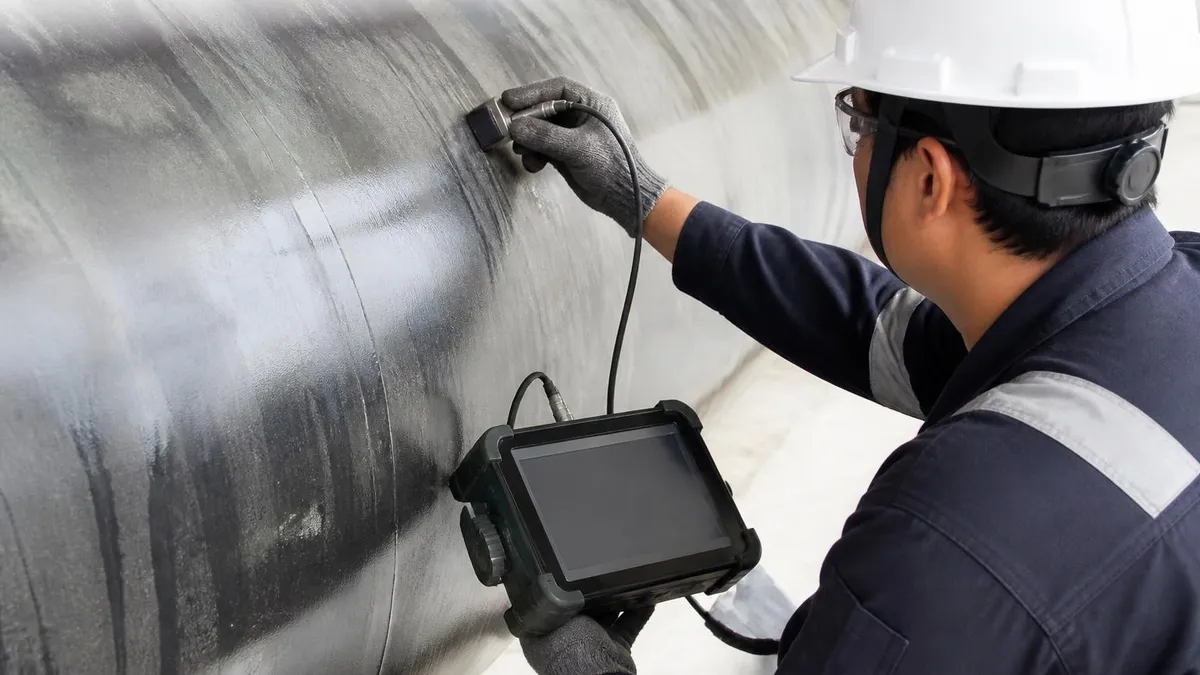
NDT Training: Complete Guide to Non-Destructive Testing Certification Courses in 2026
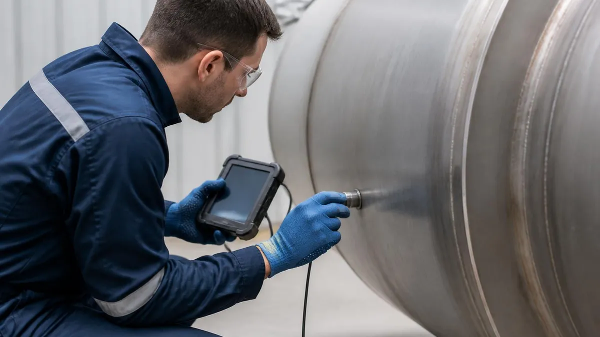
What Is NDT? A Complete Guide to Non-Destructive Testing in 2026
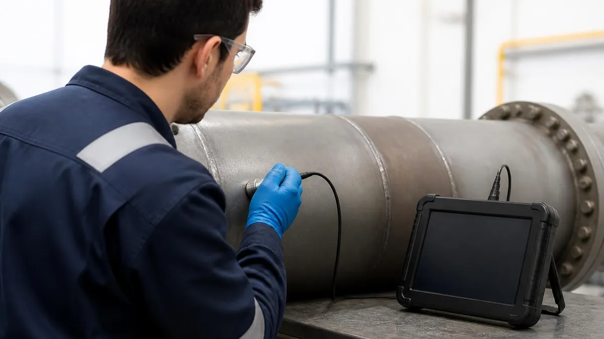
Indeed NDT Jobs: Complete Guide to Finding Non-Destructive Testing Careers in 2026

Complete Non-Destructive Testing List: Every NDT Method Explained

Crane NDT Inspection: Complete Guide to Non-Destructive Testing for Lifting Equipment
About the Author

Educational Psychologist & Academic Test Preparation Expert
Columbia University Teachers CollegeDr. Lisa Patel holds a Doctorate in Education from Columbia University Teachers College and has spent 17 years researching standardized test design and academic assessment. She has developed preparation programs for SAT, ACT, GRE, LSAT, UCAT, and numerous professional licensing exams, helping students of all backgrounds achieve their target scores.