HVAC Filter Drier: The Complete Guide to Function, Sizing, Installation, and Replacement for Refrigeration and Air Conditioning Systems
🔎 Filter drier HVAC guide covering function, sizing, installation, replacement timing, and troubleshooting for refrigeration and AC systems.

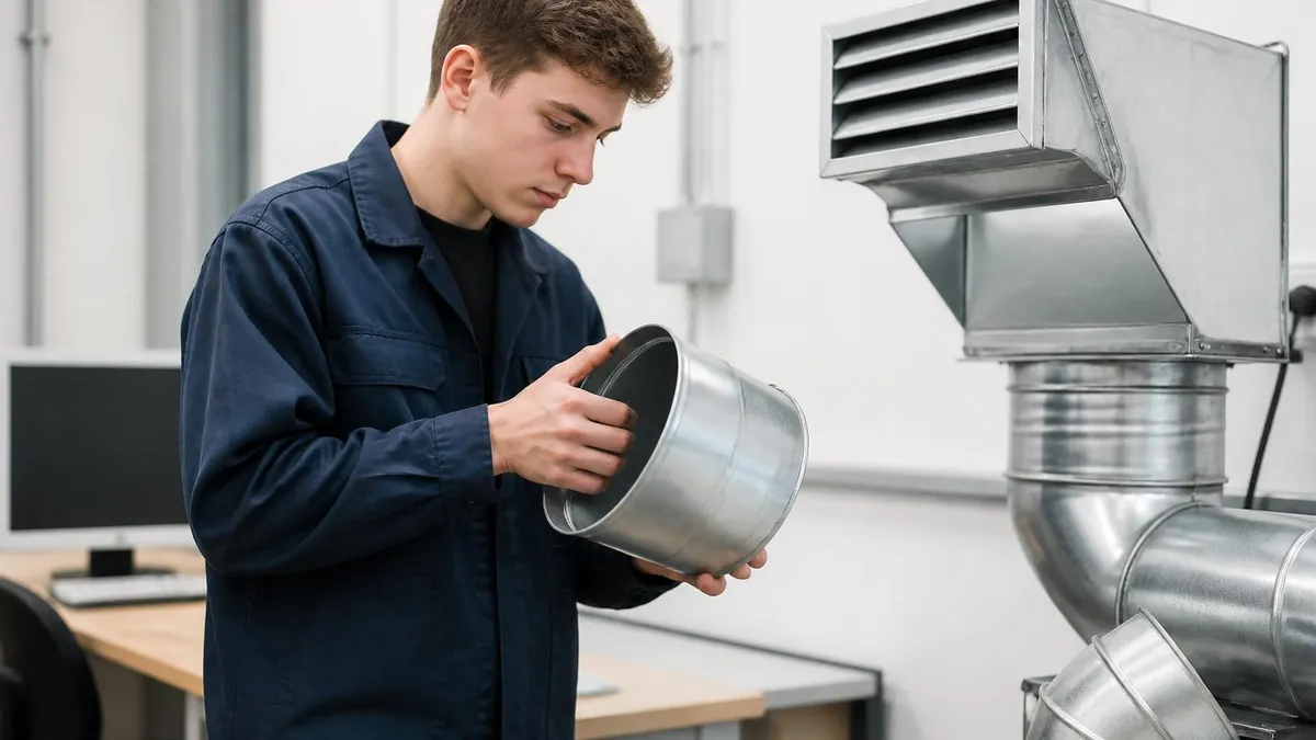
The filter drier hvac component is one of the smallest parts inside a refrigeration or air conditioning system, yet it carries enormous responsibility. Roughly the size of a soda can, this sealed cylinder sits in the liquid or suction line and quietly removes moisture, acids, and particulate contaminants from the refrigerant stream. Without it, even a well-built system would degrade in months as water reacted with refrigerant and oil to form corrosive sludge, copper plating, and acid burnout in the compressor windings.
Technicians often call the filter drier the system's kidney, and the comparison is accurate. Like a kidney, it traps harmful substances before they circulate to sensitive components. Compressors are expensive, expansion valves are precise, and capillary tubes are easily clogged. The drier protects all three by holding back debris from brazing operations, factory swarf, residual moisture from poor evacuation, and acids formed by mild thermal breakdown of polyolester or mineral oils.
Most residential and light commercial systems use a sealed, brazed-in liquid line drier installed just downstream of the condenser. Larger commercial and supermarket racks frequently add a replaceable-core shell, sometimes paired with a suction line drier during cleanup after a compressor burnout. Each configuration serves the same fundamental purpose, but the design choices around desiccant type, flow direction, and core media differ depending on refrigerant chemistry and expected contamination load.
The shift from R-22 to R-410A, R-32, R-454B, and other HFC and HFO blends has changed what a drier must handle. Modern POE lubricants are hygroscopic, meaning they absorb atmospheric moisture aggressively the moment a system is opened. A drier rated for HFC service typically contains a blend of molecular sieve and activated alumina, balancing water capacity with acid neutralization. Selecting the wrong desiccant for the wrong refrigerant can cause the drier itself to release contaminants.
Codes and best practices treat the drier as a mandatory replacement item any time the refrigerant circuit is opened. ASHRAE, the Air-Conditioning Contractors of America, and every major OEM service manual agree on this point. Even a brief exposure to ambient air loads moisture into the system that the existing drier cannot reliably absorb, especially if it has already been in service for several seasons.
This guide explains how filter driers work, how to size and install them correctly, when to replace them, and how to diagnose problems they reveal. It is written for installers, service technicians, and serious DIY homeowners studying for exams or working alongside a licensed professional. For broader system context, see our overview of HVAC Solutions which covers how the drier fits into the full refrigeration cycle alongside compressors, condensers, metering devices, and evaporators.
By the end of this article, you should be able to look at any split system, packaged unit, or rack and identify the drier, judge whether it needs replacement, choose the right model, and install it without introducing new contamination. The stakes are high: a single careless drier swap can flood a system with moisture and shorten compressor life by years.
Filter Drier HVAC by the Numbers

How a Filter Drier Works
Molecular sieve beads trap water molecules in their crystalline pore structure, while activated alumina captures acids formed by oil and refrigerant breakdown. The desiccant is held inside a steel shell using compression springs and felt pads.
A fine mesh or felt pad on the outlet side captures solid debris such as brazing flux, copper oxide flakes, metal shavings, and varnish particles. This protects downstream metering devices from clogging and compressor valves from scoring.
During normal operation small amounts of refrigerant break down into hydrochloric and hydrofluoric acids, especially under heat stress. Activated alumina chemically binds these acids, keeping the lubricant pH stable and preventing motor winding insulation damage.
Most driers are unidirectional, marked with an arrow showing refrigerant flow from inlet to outlet. Bi-flow driers used in heat pumps contain internal check valves that route refrigerant through the desiccant in the same direction regardless of mode.
Sizing a filter drier correctly is the difference between a quiet, efficient system and one that struggles with pressure drop, starves the metering device, or fails to remove contamination fast enough. The two primary sizing variables are tonnage capacity and line size. Manufacturers publish capacity tables based on refrigerant type, application (liquid line versus suction line), and acceptable pressure drop at design conditions. A drier rated for three tons on R-410A in a liquid line application is not interchangeable with the same physical size used in suction service.
Begin with the system's nominal tonnage and the refrigerant in use. Liquid line driers are sized so pressure drop stays under about two PSI at full load, since any meaningful pressure drop here can cause flash gas at the metering device inlet, hurting capacity and efficiency. Suction line driers are sized for even lower drop, typically under one PSI, because suction pressure losses translate directly into reduced compressor capacity and higher discharge temperature.
Connection size matters as much as capacity. A three eighths inch flare drier on a half inch liquid line creates an unnecessary restriction and a leak-prone reducer joint. Match the drier's inlet and outlet to the existing tubing whenever possible, using sweat fittings for permanent installations and flare or rotalock fittings where future service access is required. Many techs keep a sizing chart in their service truck cross-referencing tonnage, refrigerant, and connection size.
Refrigerant chemistry drives desiccant selection. HFC and HFO refrigerants paired with POE oil demand a high-water-capacity molecular sieve, typically a blend marked XH7, XH9, or XH11 depending on the manufacturer. Older systems running R-22 with mineral oil can use simpler XH5 sieve blends. Installing an R-22 drier on an R-410A system can cause desiccant breakdown and release fines into the refrigerant stream, ruining the metering device.
Bi-flow driers are mandatory on heat pumps and any reversing system. These contain internal check valves that ensure refrigerant always flows through the desiccant in one direction, regardless of whether the unit is heating or cooling. Installing a unidirectional drier in a heat pump liquid line will trap moisture during one mode and release it during the other, which is worse than having no drier at all.
For commercial and supermarket refrigeration, replaceable core shells offer flexibility. A single shell can accept different core types, including hot gas defrost compatible cores and high acid capacity cores for post-burnout cleanup. Cores are changed without cutting tubing, reducing labor and contamination risk during periodic service. Sizing for these shells follows the same pressure drop rules but adds core count as a variable. For a deeper look at airflow and pressure considerations across the rest of the system, see our HVAC Duct Calculator guide.
Finally, never oversize a drier with the assumption that bigger is always better. An oversized liquid line drier holds excess refrigerant in the shell during off cycles, complicating charge management and slowing pulldown. The correct drier is matched to the system, not the largest one that fits in the available space.
HVAC Practice Test Questions
Prepare for the HVAC - Heating Ventilation and Air Conditioning exam with our free practice test modules. Each quiz covers key topics to help you pass on your first try.
HVAC Air Conditioning
HVAC Exam Questions covering Air Conditioning. Master HVAC Test concepts for certification prep.
HVAC Code Compliance
Free HVAC Practice Test featuring Code Compliance. Improve your HVAC Exam score with mock test prep.
HVAC Electrical Controls
HVAC Test Prep for Electrical Controls. Practice HVAC Quiz questions and boost your score.
HVAC Energy Efficiency
HVAC Questions and Answers on Energy Efficiency. Free HVAC practice for exam readiness.
HVAC Heating Systems
HVAC Mock Test covering Heating Systems. Online HVAC Test practice with instant feedback.
HVAC Load Calculations
Free HVAC Quiz on HVAC Load Calculations. HVAC Exam prep questions with detailed explanations.
HVAC Tools and Equipment
HVAC Practice Questions for HVAC Tools and Equipment. Build confidence for your HVAC certification exam.
HVAC Refrigeration
HVAC Test Online for Refrigeration. Free practice with instant results and feedback.
HVAC Safety Practices
HVAC Study Material on Safety Practices. Prepare effectively with real exam-style questions.
HVAC System Design
Free HVAC Test covering System Design. Practice and track your HVAC exam readiness.
HVAC Thermodynamics
HVAC Exam Questions covering Thermodynamics. Master HVAC Test concepts for certification prep.
Filter Drier HVAC Types Compared
Liquid line driers are the most common type and sit between the condenser outlet and the metering device inlet. They see refrigerant in its dense liquid phase, which allows high contact time with the desiccant and excellent moisture capture. Most residential split systems include a factory installed liquid line drier near the condensing unit, with a second installed in the field if the line set is opened or extended.
Because the refrigerant is liquid, particulate filtration is critical here to protect TXVs and capillary tubes. Look for driers with integrated outlet screens rated at 20 microns or finer. Pressure drop must stay minimal since any flash gas formed upstream of the metering device reduces system capacity, increases superheat, and can mimic a low charge condition during diagnostics.

Sealed vs Replaceable Core Drier: Which Is Better?
- +Sealed driers cost less upfront and are simpler to install
- +No core handling means less exposure to atmospheric moisture during service
- +Compact size fits tight residential equipment spaces easily
- +Factory sealed shells eliminate gasket leaks at shell joints
- +Standardized sweat or flare connections speed brazing
- +Ideal for residential and light commercial applications
- +Lower training requirement for installation crews
- −Entire shell must be cut out and replaced each service
- −Higher long-term cost on systems serviced frequently
- −Limited core variety compared with shell-and-core systems
- −Brazing heat can damage adjacent components if not heat-shielded
- −Cannot be opened to inspect core condition
- −Less suitable for supermarket and industrial refrigeration
- −Disposal of sealed shells generates more scrap metal waste
Filter Drier Installation Checklist
- ✓Recover existing refrigerant to EPA 608 standards before cutting any tubing
- ✓Verify drier matches refrigerant type, oil type, and system tonnage
- ✓Confirm flow direction arrow points away from condenser toward metering device
- ✓Use bi-flow drier on all heat pump and reversing valve systems
- ✓Clean tubing ends with abrasive pad and wipe with lint-free cloth
- ✓Flow dry nitrogen at 2 to 3 SCFH through tubing during brazing
- ✓Wrap drier shell in wet rag or use heat shield to protect desiccant
- ✓Use 15 percent silver brazing alloy on copper-to-copper joints
- ✓Pressure test to 300 PSI with nitrogen and leak check all joints
- ✓Pull deep vacuum to 500 microns or lower and hold for decay test
- ✓Weigh in factory specified refrigerant charge through liquid line
- ✓Document drier model, install date, and reason on service tag
A drier is a finishing tool, not a substitute for proper evacuation
Even the largest drier cannot rescue a system that was charged at 5,000 microns. Field studies show that pulling vacuum to 500 microns or lower and holding it for a fifteen minute decay test leaves the drier with reserve capacity for years of normal operation. Skipping the decay test and rushing the evacuation forces the drier to absorb moisture it was never sized to handle, leading to premature saturation and acid formation within the first cooling season.
Knowing when to replace a filter drier separates technicians who chase recurring callbacks from those whose installations run quietly for fifteen years. The clearest rule is industry-wide: any time the refrigerant circuit is opened for any reason, the liquid line drier is replaced. This applies to compressor changeouts, evaporator coil replacements, line set repairs, TXV swaps, and even repairs to a leaking Schrader valve if the system has been open for more than a few minutes.
The reasoning is moisture math. Atmospheric air at average humidity carries enough water vapor that even five minutes of open exposure deposits more moisture than a saturated drier can hold. Once the desiccant reaches its water capacity it stops adsorbing and may begin releasing moisture back into the stream during off cycles, especially in hot ambient conditions where shell temperature rises and equilibrium shifts.
Beyond the open-circuit rule, several diagnostic signs point to a saturated or contaminated drier. The most reliable is temperature drop across the drier shell. Under normal operation the inlet and outlet should feel the same temperature to a calibrated hand or measure within a few degrees on an infrared thermometer. A drop of more than three degrees Fahrenheit indicates significant pressure drop, usually from particulate plugging or desiccant breakdown.
A sight glass with a moisture indicator gives a direct reading of refrigerant moisture content. Green means dry, yellow means wet, and the threshold varies by refrigerant and indicator type. A yellow reading immediately after install suggests poor evacuation. A reading that turns yellow months later points to a leak admitting moist air or a drier that has lost capacity. Either way the drier and the underlying cause must be addressed together.
Compressor burnouts demand both liquid and suction line drier replacement. A burnout releases acid, soot, and partially decomposed oil into the entire refrigerant circuit. The replacement compressor will fail within months if these contaminants are not removed. Best practice is to install oversized cores in a replaceable shell, run the system for 48 hours, then check oil acidity and replace cores as needed until levels normalize.
System age also influences replacement decisions. A drier from a fifteen year old system has been through thousands of thermal cycles and may have absorbed moisture from undetected micro leaks over time. When servicing older equipment for any reason, even non-refrigerant work like blower motor replacement, consider proposing drier replacement as a low-cost insurance against premature compressor failure. Pair this discussion with a review of overall system health, which can include checking distribution components like HVAC Vents and return pathways.
Finally, drier replacement is mandatory after any refrigerant retrofit. Converting from R-22 to R-407C, R-422D, or other retrofit blends introduces new oil chemistry and new moisture sensitivity. The legacy drier was sized and specified for the original refrigerant and may not be compatible with the retrofit. Always specify a drier rated for the new refrigerant family before charging.

A drier that has been exposed to atmospheric air, even briefly, cannot be reused safely. The desiccant rapidly absorbs ambient moisture and may exceed its capacity before installation. Always install a fresh drier from a sealed package, and braze it in within fifteen minutes of breaking the seal. Older driers found on a shelf or in a service van should be considered suspect unless their packaging is intact and the manufacturing date is within two years.
Troubleshooting a filter drier starts with feeling the shell during steady state operation. On a properly functioning liquid line drier, inlet and outlet temperatures should be nearly identical. Any noticeable temperature drop across the shell indicates flow restriction, which on a drier means particulate plugging, ice formation from internal moisture freezing, or desiccant breakdown that has packed fine debris into the outlet screen. The greater the drop, the more urgent the replacement.
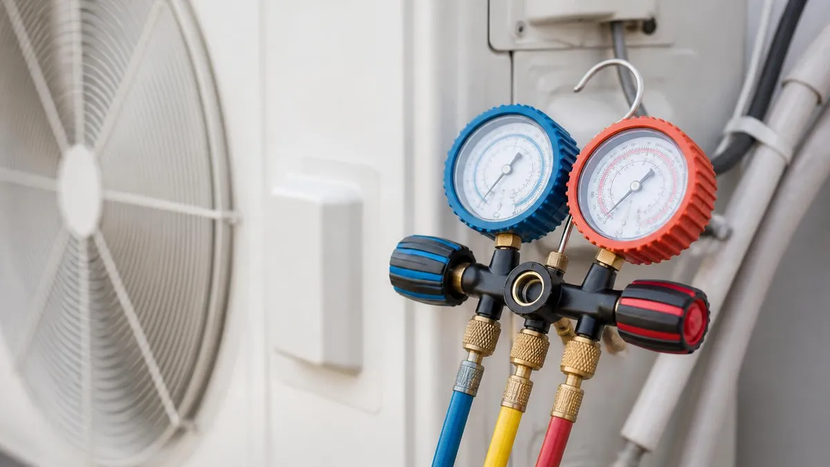
Pressure measurement gives a more precise diagnostic. Connecting gauges to ports upstream and downstream of the drier reveals the exact pressure differential under load. Most manufacturers publish maximum acceptable drop for each drier model, usually between one and three PSI for liquid line service. Exceeding this number indicates the drier should be replaced even if the system still appears to cool. Acting early prevents secondary damage to the metering device and compressor.
A drier that frosts on the outlet side during operation is a classic sign of severe restriction. The pressure drop across the restriction causes refrigerant to flash inside or just downstream of the drier, lowering temperature below ambient and condensing water vapor from the air onto the shell. This is almost always an emergency condition requiring immediate shutdown and drier replacement, often paired with a deeper investigation into what caused the contamination.
Sight glass indicators are the second key diagnostic tool. A moisture indicator that reads wet under stable operating conditions confirms the drier has either failed or been overwhelmed. Before condemning the drier, verify the system has been running long enough for the indicator to stabilize, typically thirty minutes at design conditions. New systems sometimes show transient wet readings during pulldown that clear within an hour as the drier absorbs residual moisture.
Acid testing the lubricant provides a third independent measurement. Field acid test kits use color change reagents to indicate acid levels in the oil. A reading above the safe threshold means the drier is not keeping up with acid formation, either because the desiccant is saturated or because acid is being generated faster than expected. The latter usually points to compressor overheating, contamination, or refrigerant leakage allowing air ingress.
When diagnosing repeated drier failures on the same system, look for root causes rather than continuing to swap shells. Common culprits include slow leaks admitting moist air, undersized condensers causing high discharge temperatures and accelerated oil breakdown, and improper evacuation procedures during prior service. A pattern of acid contamination across multiple drier replacements is a strong indicator that the compressor itself is approaching failure and should be evaluated. If you suspect deeper issues, consulting qualified HVAC Contractors for a second opinion is well worth the cost.
Finally, document every drier replacement on a service tag attached to the equipment. Include date, model number, refrigerant type, and reason for replacement. This history is invaluable for future technicians and for warranty claims. Patterns across multiple service visits often reveal underlying problems that no single visit would catch on its own.
Practical field tips can save hours of rework and prevent the costly mistakes that ruin otherwise solid installations. The first and most important habit is to keep driers sealed until the moment they go into the line. Once the protective end caps come off, the clock is running. Molecular sieve will pull moisture from room air at a rate that depends on humidity but is always faster than expected. Aim to braze within fifteen minutes of breaking the package seal.
Heat shielding during brazing protects the desiccant from thermal damage. Wrap the drier shell in a wet rag, soaked but not dripping, before applying flame to either joint. The water absorbs heat and keeps the shell below the temperature at which desiccant binders break down. Some technicians use commercial heat sink paste or a metal heat shield instead, both of which work well. Direct flame on the shell itself, even briefly, can ruin a brand new drier.
Nitrogen flow during brazing is the single most effective contamination prevention practice. A trickle of dry nitrogen at two to three SCFH through the tubing displaces air and prevents copper oxide formation on the inside walls. Without this purge, brazing produces black flaky scale that breaks loose during operation and clogs the drier outlet screen within weeks. The cost of a tank of nitrogen is trivial compared with a callback to replace a clogged drier.
Choose connection types deliberately. Sweat connections are permanent, leak free, and ideal for residential equipment that rarely needs servicing. Flare connections allow tool-free removal but require precise flaring technique and proper torque to avoid leaks. Rotalock and similar mechanical fittings simplify service on commercial racks but add cost and potential leak points. Mixing connection types on the same drier, such as sweat inlet and flare outlet, is fine when the application calls for it.
Develop a personal sizing reference that you carry in your service truck. Print or laminate the manufacturer tables for the drier brands you use most, organized by refrigerant and tonnage. This saves time on every job and reduces the chance of grabbing the wrong drier from inventory. Many supply houses provide pocket cards or apps, but a personally annotated chart marked with your most common applications is faster in the field.
Train apprentices to inspect every drier package before installation. Check the manufacturing date, the refrigerant compatibility marking, the connection sizes, and the flow direction arrow. A drier that has been sitting in a hot van for two summers is suspect even if the packaging looks intact. Building this habit early prevents the worst kind of mistake, the one that is not discovered until months later when the compressor fails. If you ever need fast assistance with a contaminated system, knowing local HVAC repair services near me can speed the response.
Finally, keep a small inventory of common drier sizes in the service truck. The two most common residential sizes plus a bi-flow option will cover most callouts without a parts run. Stocking driers for the refrigerants you service most frequently, with a fresh rotation every six months, ensures you never install an old drier and never miss an opportunity to protect a system that was opened for any reason.
HVAC Questions and Answers

HVAC Solutions: The Complete Guide to Heating, Cooling, and Indoor Air Quality Systems for Homes and Buildings

HVAC Vents: The Complete Homeowner's Guide to Types, Sizing, Placement, and Airflow Optimization
HVAC Duct Calculator: The Complete Guide to Sizing Ductwork for Airflow, Static Pressure, and System Efficiency
Certified HVAC Contractors: How to Find, Vet, and Hire the Right Professional for Your Home or Business

Best HVAC Repair in Bandon, OR: Local Services Near Me Guide
About the Author
NATE Certified HVAC Technician & Licensing Exam Trainer
Universal Technical InstituteMike Johnson is a NATE-certified HVAC technician and EPA 608 universal-certified refrigerant handler with a Bachelor of Science in HVAC/R Technology. He has 19 years of commercial and residential HVAC installation and service experience and specializes in preparing technicians for NATE certification, EPA 608, A2L refrigerant safety, and state HVAC contractor licensing examinations.