
HVAC Discharge Line: What It Is, How It Works, and Why It Matters for Every Tech
Master the HVAC discharge line — how it works, common failures, pressure specs, and repair tips. ✅ Essential knowledge for every HVAC technician.
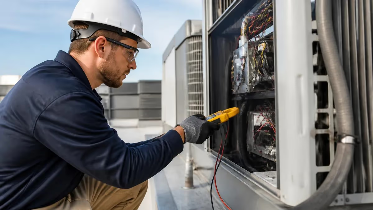
The HVAC discharge line is one of the most critically important components in any refrigeration or air conditioning system, yet it remains one of the least discussed during basic training. Also called the hot gas line, this high-pressure copper or steel tube carries superheated refrigerant vapor from the compressor outlet directly to the condenser coil. Understanding exactly what happens inside this line — including the temperatures, pressures, and flow dynamics — is essential for diagnosing compressor problems, refrigerant overcharge conditions, and condenser inefficiencies before they cause expensive failures.
Every air conditioning system operates on a continuous thermodynamic cycle that relies on the discharge line to bridge the high-pressure side between the compressor and condenser. When the compressor completes its compression stroke, refrigerant exits at temperatures that can easily exceed 180°F to 220°F in a properly functioning residential system, and even higher in commercial applications under heavy load. The line must be properly insulated, correctly sized, and free from kinks or restrictions to maintain system efficiency and protect compressor longevity over years of operation.
Technicians who understand the hvac discharge line can diagnose system problems far more accurately than those who rely solely on suction pressure readings. Discharge temperature is a powerful diagnostic tool because it responds almost immediately to changes in refrigerant charge, condenser airflow, compressor valve condition, and ambient temperature. A superheat calculation at the discharge port — combined with a high-side pressure reading — tells a skilled tech more about system health than almost any other single measurement available in the field.
Residential split systems, heat pumps, rooftop packaged units, and commercial chillers all use discharge lines, though the sizing, material, and routing requirements vary significantly by application. A residential 3-ton split system might use 3/8-inch discharge tubing, while a large commercial rooftop unit may require 7/8-inch or even 1-1/8-inch copper or black steel pipe depending on the refrigerant type and total system capacity. Getting the line size wrong at installation creates velocity problems that either prevent oil return to the compressor or generate excessive pressure drop that reduces system efficiency.
Discharge line problems typically manifest as high head pressure, compressor overheating, nuisance high-pressure cutouts, or repeated compressor failures over a relatively short service life. In many cases, a technician called out for a "burned compressor" will discover that the root cause was actually a discharge line restriction, improper insulation that allowed heat soak back into the suction side, or a failed check valve that allowed liquid refrigerant to flow backward into the compressor during off cycles. Understanding the discharge line is therefore inseparable from understanding compressor protection.
Refrigerant type also plays a major role in how discharge lines behave and must be specified. R-410A systems operate at significantly higher pressures than older R-22 systems, meaning discharge lines in modern equipment see working pressures that can exceed 400 PSIG under adverse conditions. R-32 and the newer low-GWP refrigerants like R-454B bring their own pressure-temperature characteristics that technicians must understand to safely and accurately diagnose discharge line behavior. The era of universal rules of thumb is largely over — today's technician needs refrigerant-specific knowledge.
This article provides a comprehensive look at HVAC discharge lines from every angle: construction and materials, normal operating parameters, common failure modes, diagnostic techniques, repair procedures, and the code requirements that govern installation. Whether you are preparing for an EPA 608 exam, studying for a state contractor license, or simply trying to sharpen your field skills, the information here will give you a solid, practical foundation for working with discharge lines safely and confidently every day on the job.
HVAC Discharge Line by the Numbers
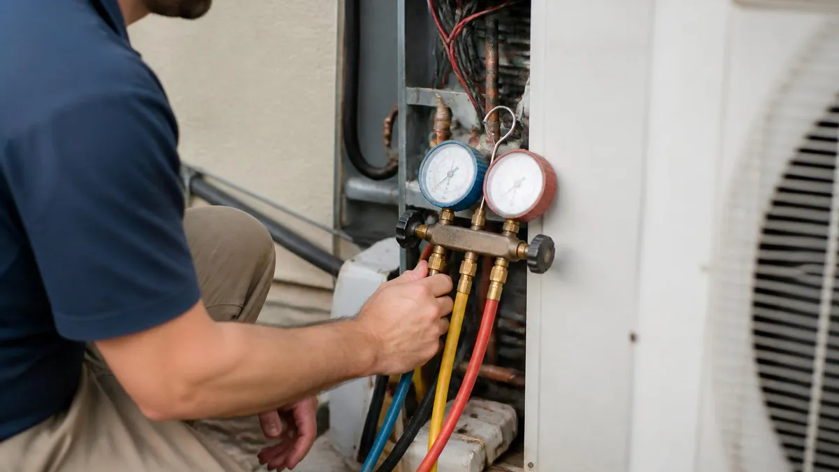
How the Discharge Line Fits Into the Refrigeration Cycle
Compression Stroke
Discharge Line Transit
Condenser Entry
Heat Rejection
Expansion and Evaporation
Normal operating parameters for an HVAC discharge line vary by refrigerant type, system capacity, and ambient conditions, but certain benchmarks apply across most residential and light commercial applications. For an R-410A system operating in cooling mode with an outdoor temperature around 95°F and indoor return air at 75°F dry bulb, a healthy discharge line should measure approximately 180°F to 220°F at a point roughly six inches from the compressor outlet. Discharge pressure on the high side should sit in the range of 380 to 420 PSIG depending on the specific equipment and refrigerant blend characteristics.
Discharge superheat — the temperature above the saturation point at a given discharge pressure — is the most telling single measurement available on the high side of any system. Healthy discharge superheat typically falls between 50°F and 70°F in residential cooling applications. Values below 50°F may suggest refrigerant overcharge, a failing compressor, or slugging from liquid carryover on the suction side. Values above 80°F or 90°F often indicate refrigerant undercharge, high compression ratios caused by a dirty condenser, or compressor valve inefficiency that forces the compressor to work harder to move the same mass of refrigerant.
Line sizing for discharge piping follows ASHRAE guidelines and manufacturer specifications that balance two competing concerns: pressure drop and oil return velocity. If the discharge line is oversized, refrigerant velocity drops too low to carry entrained compressor oil droplets back to the condenser and eventually through the system. This leads to oil logging in low spots of the line and, over time, compressor oil starvation. If the line is undersized, excessive pressure drop raises the effective compression ratio, reducing system capacity and efficiency while increasing compressor discharge temperature beyond safe limits.
Vertical discharge risers deserve special attention because gravity works against oil return in these sections. ASHRAE recommends maintaining a minimum velocity of 1,000 feet per minute in vertical risers to ensure reliable oil entrainment. In systems where capacity can vary significantly — such as those using variable-speed compressors or multi-stage equipment — a double riser configuration may be required. A double riser uses two parallel vertical pipes where one pipe traps oil at low capacity until enough accumulates to periodically flush upward, preventing long-term oil starvation at the compressor during part-load operation.
Material selection for discharge lines has evolved alongside refrigerant technology. Traditional ACR (air conditioning and refrigeration) copper tubing — types L and K — remains the most common choice for residential and light commercial work because of its excellent thermal conductivity, ease of brazing, and proven compatibility with most refrigerants and lubricating oils. However, some newer refrigerants and synthetic lubricants require special consideration for material compatibility, particularly where moisture ingress or chlorine presence could accelerate internal corrosion over the service life of the system.
For larger commercial systems and rooftop units using ammonia refrigerant, black steel pipe with threaded or welded connections replaces copper entirely because ammonia reacts with copper alloys to form copper-ammonia complexes that attack metal surfaces. Carbon dioxide (CO2) transcritical systems operate at extraordinarily high discharge pressures — sometimes exceeding 1,500 PSIG in the gas cooler circuit — requiring specially rated high-pressure tubing and fittings that far exceed the pressure ratings used in conventional HFC systems. Technicians transitioning from residential to commercial refrigeration work must be aware of these dramatic differences.
Insulating the discharge line may seem counterintuitive given that it is already very hot, but insulation serves an important purpose in specific installation scenarios. When a discharge line runs adjacent to a suction line in an unconditioned attic or mechanical room, heat radiating from the discharge line can add unwanted superheat to the suction line before refrigerant reaches the compressor. This phenomenon — called heat soak or heat transfer between lines — reduces system efficiency and can contribute to elevated compressor discharge temperatures that shorten compressor life. Separating the lines physically or insulating the discharge line prevents this heat migration.
Discharge Line Failure Modes: Symptoms, Causes, and Fixes
Abnormally high discharge temperatures — generally readings above 225°F at the compressor outlet — are one of the most common and serious problems a discharge line can reveal. The root causes range from low refrigerant charge and dirty condenser coils to non-condensable gases in the system, failed compressor discharge valves, or a discharge line restriction that creates excessive back-pressure. Each scenario raises the compression ratio beyond design limits, forcing the compressor to work harder and generating more heat per unit of refrigerant moved through the system.
Diagnosing the exact cause requires a systematic approach: measure discharge superheat first, then check subcooling at the liquid line, inspect condenser airflow, verify refrigerant charge against manufacturer specifications, and finally perform a compressor valve efficiency test if the other checks come back normal. High discharge temps left unaddressed destroy compressor lubricant, which begins to break down and carbonize at temperatures above 250°F, leaving deposits on valve seats and discharge ports that accelerate wear and ultimately cause compressor failure within a surprisingly short time frame.
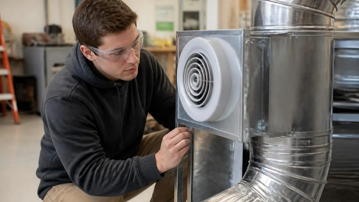
Discharge Line Diagnostics: Manual Gauges vs. Digital Manifolds
- +Digital manifolds display discharge superheat calculation automatically, eliminating math errors in the field
- +Electronic pressure-temperature charts cover hundreds of refrigerant blends without carrying printed charts
- +Wireless digital manifolds keep the technician away from energized equipment during live testing
- +Real-time data logging captures pressure fluctuations that indicate intermittent valve problems
- +Higher accuracy transducers in digital manifolds reduce misdiagnosis from gauge calibration drift
- +Integration with manufacturer apps provides instant access to system-specific diagnostic criteria
- −Digital manifolds cost significantly more upfront than traditional mechanical gauge sets
- −Battery dependency means digital tools can fail at critical moments without a charged backup
- −Technicians who rely on digital readouts may not develop intuitive feel for system behavior
- −Transducer connections can introduce refrigerant loss if fittings are not properly maintained
- −Software updates and app compatibility issues can render expensive tools temporarily unusable
- −Mechanical gauges remain more reliable in extreme temperature environments that affect electronics
Discharge Line Inspection Checklist for Service Calls
- ✓Measure discharge line temperature at the compressor outlet before attaching gauges to establish baseline superheat.
- ✓Record high-side pressure and compare to the saturation temperature of the installed refrigerant at current conditions.
- ✓Calculate discharge superheat: subtract saturation temperature at discharge pressure from measured discharge line temperature.
- ✓Inspect the full visible length of the discharge line for kinks, sharp bends, oil staining, and physical damage.
- ✓Verify that the discharge line is not in contact with the suction line in a way that transfers heat without insulation.
- ✓Check all brazed connections and flare fittings for signs of oil weeping, which indicates a refrigerant leak at the joint.
- ✓Confirm that vertical discharge risers are sloped or trapped correctly according to manufacturer installation diagrams.
- ✓Test the discharge muffler if installed — a collapsed muffler creates a restriction that mimics other high-side problems.
- ✓Verify that the discharge line diameter matches the specification for the equipment model, capacity, and total line length.
- ✓Document all measurements and compare against manufacturer performance data tables for the specific operating conditions found.
Discharge Superheat Below 50°F Is a Red Flag
If your discharge superheat reading falls below 50°F on a residential R-410A system, stop and investigate before proceeding. Low discharge superheat — especially combined with low suction superheat — often indicates refrigerant overcharge or liquid slugging that can destroy compressor valves within a single operating season. Always verify charge using the manufacturer's charging chart, not assumptions based on suction pressure alone.
Repairing or replacing a discharge line requires careful preparation to avoid introducing contaminants into a system that has already experienced a problem. Before cutting into any discharge line, the refrigerant charge must be properly recovered using EPA-certified recovery equipment — never vented to atmosphere regardless of the circumstances, as this violates Section 608 of the Clean Air Act and carries substantial civil penalties.
Once the system is fully recovered and the pressure has been verified at zero on both high and low sides, the technician can begin evaluating whether a section repair or full line replacement is the most practical approach.
Brazing copper discharge lines requires specific technique and filler material selection. Most HVAC industry standards specify the use of BCuP-5 (15% silver brazing alloy) or a higher-silver-content alloy such as Sil-Fos for copper-to-copper joints. The critical best practice during brazing is to flow dry nitrogen through the line at low pressure — typically 2 to 5 CFH — to prevent the formation of copper oxide scale on the interior of the tube.
This scale, called mill scale or fire scale, flakes off when the system starts and can lodge in metering devices, filter-drier cores, and compressor valve ports, creating exactly the kind of restriction that may have caused the original problem.
After completing all braze joints and allowing the assembly to cool completely, the next step is to pressure test the new section using dry nitrogen — never oxygen or compressed air, which create explosion hazards when mixed with refrigerant oil residue. Pressure testing should be performed at a minimum of the system's rated high-side working pressure, typically 300 to 450 PSIG depending on the refrigerant.
Hold the test pressure for a minimum of 15 to 30 minutes while checking every fitting and braze joint with an electronic leak detector or calibrated soap solution to confirm a bubble-tight seal before proceeding to the evacuation phase.
Deep vacuum evacuation is non-negotiable after any discharge line repair that opened the refrigerant circuit. Industry standards require pulling the system down to 500 microns or lower — measured with a dedicated electronic micron gauge, never estimated from compound gauge readings, which are far too imprecise at these low pressures.
A common best practice is the triple-evacuation method: pull to 500 microns, break the vacuum with dry nitrogen to 2 PSIG, allow nitrogen to absorb remaining moisture for 10 to 15 minutes, then pull vacuum again to 300 microns or lower before charging. This process removes far more moisture than a single-pull evacuation and dramatically reduces the risk of acid formation in the refrigerant circuit.
When replacing a full discharge line run — as opposed to repairing a short section — it is worth reviewing the original installation design against current ASHRAE standards and the manufacturer's current installation data. Equipment manufacturers update their installation documents periodically, and the guidance for newer high-efficiency equipment or refrigerant conversions may differ from what was used when the system was originally installed. Line sizing that was acceptable for an older, lower-efficiency compressor may not meet velocity requirements for a modern variable-speed unit, and installing the same diameter line could perpetuate oil return problems.
Discharge line replacement on heat pump systems introduces an additional consideration: the reversing valve. In heat pump operation, the discharge and suction sides of the system swap functions between heating and cooling mode, meaning the discharge line in cooling mode becomes a path for high-pressure hot gas in heating mode as well. Technicians must ensure that any replaced section or new routing is suitable for both operating modes and that check valves, where used, are compatible with bidirectional flow requirements specific to heat pump refrigerant circuit design.
Documentation is the final and often neglected step in any discharge line repair. Recording pre-repair and post-repair measurements — including discharge temperature, discharge pressure, discharge superheat, subcooling, suction superheat, and ambient conditions — creates a baseline that the next technician can use for comparison during future service calls. Good documentation also demonstrates to the customer that a systematic diagnostic process was followed and that the repair was validated by performance data, not simply assumed to be successful because the system started running after the work was completed.

Pressurizing an HVAC system with compressed air introduces moisture and creates a potentially explosive mixture with residual refrigerant oil inside the discharge line. Oxygen is even more dangerous — it reacts violently with refrigerant oil under pressure. Always use dry nitrogen from a properly labeled cylinder with a pressure regulator when performing leak or pressure tests on any part of the refrigerant circuit.
Code requirements governing HVAC discharge line installation come from multiple overlapping sources: the International Mechanical Code (IMC), ASHRAE Standards 15 and 34, manufacturer installation manuals, and local jurisdiction amendments that sometimes impose requirements stricter than the model codes. Technicians and installing contractors must be aware of which documents have authority in their specific jurisdiction and how conflicts between them are resolved — typically the more restrictive requirement applies when local amendments and model codes disagree on a specific point of installation practice.
ASHRAE Standard 15, the Safety Standard for Refrigeration Systems, governs the mechanical and safety aspects of refrigerant piping including discharge lines. Key provisions include requirements for pressure relief devices on the high side of any system where the compressor could be isolated from the condenser by a service valve, minimum clearances from heat sources and ignition sources, requirements for pipe supports and hangers at specified intervals, and specifications for material compatibility with the refrigerant and lubricant combination installed in the system. Many of these requirements become critical examination topics for contractor license exams.
Pipe support requirements for discharge lines deserve specific attention because improperly supported piping is a common deficiency found during code inspections. Copper discharge lines must be supported at intervals not to exceed those specified in the IMC, which generally requires a support every four to six feet depending on pipe diameter. Supports must allow for thermal expansion and contraction without creating stress concentrations at braze joints or fittings. Rigid supports that prevent all movement can cause fatigue cracks at fittings over years of thermal cycling, particularly in equipment that cycles frequently in climates with wide temperature swings between seasons.
Penetrations through fire-rated walls and floors must be firestopped using UL-listed materials appropriate for the pipe diameter, construction type, and fire rating of the assembly being penetrated. Many HVAC technicians focus on the refrigerant circuit aspects of discharge line installation and overlook the building code requirements for penetration protection, creating a liability exposure for their employer and a potential safety hazard for building occupants. Inspectors in commercial and multifamily residential buildings routinely cite improper firestopping of refrigerant line penetrations as a significant deficiency during mechanical inspections.
Labeling requirements for discharge lines in commercial applications require that high-pressure refrigerant piping be marked to identify the refrigerant type, the direction of flow, and the operating pressure range. ANSI A13.1 provides the color coding and labeling standards used in most commercial mechanical rooms. These markings serve a critical safety function: emergency responders and maintenance personnel who encounter an unknown refrigerant system need to quickly identify the refrigerant type to avoid using incompatible materials, applying incorrect pressures during service, or making safety decisions based on the wrong physical properties during an emergency refrigerant release event.
Seismic restraint requirements apply to HVAC piping — including discharge lines — in seismic design categories C through F as defined by the International Building Code. In earthquake-prone regions like California, the Pacific Northwest, and parts of the intermountain West, discharge lines above a certain diameter and length must be braced with sway bracing systems designed to prevent the piping from swinging and failing at braze joints during seismic events.
Failing to install required seismic bracing is a serious code violation and can result in project rejection during inspection, costly rework, and — in worst-case scenarios — refrigerant releases during earthquakes that endanger building occupants.
Finally, technicians pursuing career advancement into project management, estimating, or systems design should understand that discharge line design is formally governed by ASHRAE Handbook — Refrigeration, particularly the chapter on system piping. This reference provides detailed tables for line sizing across dozens of refrigerants, elevation correction factors for long vertical runs, guidance on double-riser design, and oil return calculations for variable-capacity equipment. The technician who takes the time to study this material — rather than relying entirely on rule-of-thumb line sizing — brings a fundamentally different and more valuable level of engineering literacy to any installation or design project.
Preparing effectively for HVAC certification exams and contractor license tests requires understanding the discharge line not just as a physical component but as a diagnostic window into the entire refrigeration system. Exam questions frequently present scenarios where a technician takes field measurements and must identify the most likely cause of a system problem. The ability to interpret discharge temperature, discharge pressure, and calculated discharge superheat — and to connect those readings to specific system faults — is tested on nearly every major HVAC credentialing exam in the United States, from EPA 608 to NATE Core and specialty certifications.
A particularly common exam scenario presents a system with high discharge temperature and high discharge pressure simultaneously. Candidates who have memorized isolated facts may struggle to identify the cause, but those who understand the thermodynamic relationships involved will quickly recognize this combination as consistent with a dirty condenser, non-condensable gases in the system, or a restricted discharge line — all conditions that raise the condensing pressure and force the compressor to work against a higher head pressure than the system was designed to handle.
Understanding why these readings occur together, rather than simply memorizing the answer, allows the candidate to correctly answer variations of this question regardless of how it is phrased.
Contrast this with the low-discharge-temperature, low-discharge-pressure scenario, which typically points to refrigerant undercharge, a failed compressor with leaking discharge valves, or a restriction on the low side that starves the compressor of refrigerant mass flow. Each combination of high-side readings tells a specific diagnostic story, and building the mental model to read these stories is the core skill that separates competent technicians from truly excellent diagnosticians. Study programs that emphasize conceptual understanding alongside memorization produce technicians who perform better on exams and provide better service in the field.
Practice questions specifically targeting discharge line knowledge should cover a range of difficulty levels. Entry-level questions might ask the technician to identify the correct location of the discharge line in a system diagram. Intermediate questions test knowledge of normal pressure-temperature relationships, proper brazing procedures, and oil return velocity requirements. Advanced questions may present multi-variable scenarios where the candidate must prioritize possible causes based on the full set of measurements provided, ruling out less likely causes based on specific readings that contradict them. Working through questions at all three levels builds the layered knowledge structure that exam designers test.
Time management during certification exams is another area where discharge line topics deserve attention. Because discharge line diagnostics require multi-step reasoning — measuring, calculating superheat, comparing to specifications, ruling out alternative causes — candidates who are not well prepared often spend excessive time on these questions and run short of time for questions they could answer quickly. Practicing discharge line scenario questions under timed conditions builds the mental shortcuts and pattern recognition that allow confident, rapid answers during the actual exam without sacrificing accuracy.
The NATE (North American Technician Excellence) exams, in particular, heavily emphasize refrigerant system diagnostics including discharge line interpretation. The Air Conditioning specialty exam and the Heat Pump specialty exam both include significant content on high-side diagnostics that directly tests discharge line knowledge. Similarly, the EPA 608 Universal exam tests safe handling of refrigerants in systems including discharge line procedures during service. Candidates who study these specific content areas rather than trying to memorize every fact about HVAC systems generally achieve better scores because they build depth in the areas most heavily weighted on the actual credential exams.
Supplementing textbook study with hands-on practice on live equipment — or on system simulators where available — dramatically accelerates the development of discharge line diagnostic skills. Reading about discharge superheat calculation is valuable, but physically measuring a discharge line on a system with a known fault and working through the diagnostic process builds a kind of procedural memory that text alone cannot replicate.
Many HVAC schools and training centers maintain laboratory systems specifically for this kind of practice, and technicians seeking to improve their credentials should take advantage of every opportunity for hands-on discharge line work under the supervision of experienced instructors.
HVAC Questions and Answers
FCU HVAC: The Complete Guide to Fan Coil Units, How They Work, Where They Excel, and How to Choose the Right System
Finance a New HVAC System: 2026 Loans, 0% APR, and Rebates

HVAC Duct Repair: Common Issues, Costs, and DIY vs Professional
HVAC School -- Programs, Costs, and Career Paths in 2026
HVAC Advertising: The Complete Playbook for Generating Leads, Booking Calls, and Growing Your Heating and Cooling Business
About the Author

NATE Certified HVAC Technician & Licensing Exam Trainer
Universal Technical InstituteMike Johnson is a NATE-certified HVAC technician and EPA 608 universal-certified refrigerant handler with a Bachelor of Science in HVAC/R Technology. He has 19 years of commercial and residential HVAC installation and service experience and specializes in preparing technicians for NATE certification, EPA 608, A2L refrigerant safety, and state HVAC contractor licensing examinations.