FREE CSWA Drawing and Detailing Questions and Answers
A line in the plane of a circle that intersects the circle at exactly one point.
Explanation:
The term "Tangent" refers to a line in the plane of a circle that intersects the circle at exactly one point. Tangents are essential for defining the contact points between circles and other geometric shapes in technical drawings. Understanding tangents is crucial for accurately representing the relationships between different elements in engineering designs and drawings.
A thin line consisting of long and short dashes. It shows the center of holes, slots, paths of rotation, and symmetrical objects.
Explanation:
The "Center Line" is a thin line consisting of long and short dashes used to represent various elements such as the center of holes, slots, paths of rotation, and symmetrical objects in technical drawings. Center lines aid in communicating design intent, providing clarity on the location and symmetry of features within a part or assembly drawing.
A line type that represents an edge that is not directly visible.
Explanation:
"Hidden Line" represents an edge that is not directly visible in technical drawings. Hidden lines are used to indicate features or edges that are obscured by other components in the drawing, providing clarity on the internal structure or hidden details of the object. Understanding hidden lines is essential for creating accurate and informative engineering drawings.
Used to represent visible edges and outlines of the object being drawn.
Explanation:
Visible Line is used to represent visible edges and outlines of the object being drawn in technical drawings. Visible lines are essential for communicating the shape, size, and form of the object, providing clarity on its geometry and features. Understanding visible lines is fundamental for creating accurate and informative engineering drawings.
The perimeter of a circle:
Explanation:
The term "Circumference" represents the perimeter of a circle, which is the distance around the outer edge of the circle. In SOLIDWORKS, understanding circle properties like circumference is essential for accurately dimensioning and detailing circular features in technical drawings and designs.
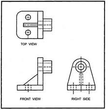
A method of representing three-dimensional objects on a plane having only length and breadth. Also referred to as Right Angle Projection.

Explanation:
"Orthographic Projection" refers to a method of representing three-dimensional objects on a plane using only length and breadth, commonly known as Right Angle Projection. In orthographic projection, different views of the object (e.g., front, top, side) are depicted in separate 2D drawings, each showing one aspect of the object's geometry. Understanding orthographic projection is crucial for creating accurate engineering drawings that communicate the design intent effectively.
A straight line from the center to the circumference of a circle or sphere.
Explanation:
Radius represents a straight line from the center to the circumference of a circle or sphere. Understanding radii is crucial for accurately dimensioning circular features in technical drawings and designs. Radii provide essential geometric information about the size and shape of circular components in engineering documentation.
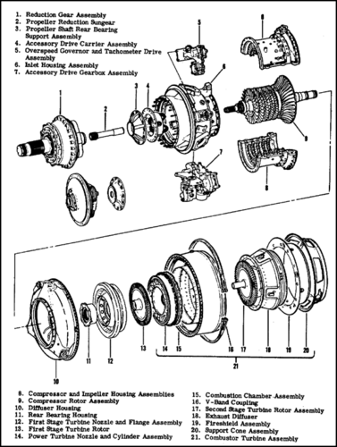
An assembly drawing in which parts are moved out of position along an axis so that each individual part is visible.

Explanation:
An exploded view is an assembly drawing where parts are moved out of their normal position along an axis to make each individual part visible. This visualization technique helps in clearly understanding the relationship between components and their assembly sequence, aiding in assembly instructions and technical documentation.
A straight line that passes from side to side through the center of a circle or sphere.
Explanation:
Diameter represents a straight line passing from side to side through the center of a circle or sphere. Understanding diameters is crucial for accurately dimensioning circular features in technical drawings and designs. Diameters provide essential geometric information about the size and shape of circular components in engineering documentation.
A table located in the bottom right-hand corner of an engineering drawing that identifies, in an organized way, all of the necessary information that is not given on the drawing itself.
Explanation:
The title block is a table typically located in the bottom right-hand corner of an engineering drawing. The title block organizes essential information such as the part name, part number, material, scale, revision history, and other details necessary for understanding and interpreting the drawing. The title block serves as a standardized format for documentation and communication in engineering drawings.
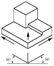
The drawing of a 3d object that shows a corner view of a figure. it is not drawn in perspective and the distances are not distorted.

Explanation:
"Isometric Drawing" refers to the drawing of a 3D object that shows a corner view of a figure without perspective distortion. Isometric drawings depict objects using parallel lines, resulting in a three-dimensional representation where all three axes are equally foreshortened. These drawings are commonly used in engineering to provide a clear and accurate depiction of objects, making them valuable for communication and visualization purposes.