FREE CSWA Part Modeling Questions and Answers
A feature that creates a base or boss, a revolved cut, or a revolved surface by revolving one or more sketched profiles around a centerline:
Explanation:
In SOLIDWORKS, the Revolve feature creates a base or boss, a revolved cut, or a revolved surface by rotating one or more sketched profiles around a centerline. This feature is commonly used to create symmetrically shaped features such as cylindrical bodies, holes, or rounded protrusions by rotating a sketch profile about an axis.
A conical-shaped recess around a hole that is often used to receive a tapered screw:
Explanation:
The Counter Sink refers to a conical-shaped recess around a hole, often used to receive a tapered screw. This feature allows the screw head to sit flush with the material surface, providing a smooth and finished appearance. Counter sinks are commonly used in various engineering and manufacturing applications for securing components together.
Appears as three gray arrows and represents the (0,0,0) coordinate of the model.
Explanation:
"Origin" appears as three gray arrows and represents the (0,0,0) coordinate of the model in SOLIDWORKS. The origin serves as the reference point for creating and positioning geometry within the modeling environment. Understanding the location and significance of the origin is essential for accurately defining the spatial relationships and dimensions of features in a part model.
A cylindrical flat-bottomed hole that enlarges another coaxial hole:
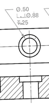
Explanation:
A counterbore is a cylindrical flat-bottomed hole that enlarges another coaxial hole. It typically provides a flat surface at the bottom of the hole, allowing a bolt head or screw to sit flush with the surface of the material. This feature is commonly used in engineering and manufacturing for applications where a smooth and flush surface is desired.
A feature that linearly projects a sketch to either add material to a part (in a base or boss) or remove material from a part (in a cut or hole).
Explanation:
The Extrusion linearly projects a sketch to either add material to a part (in a base or boss) or remove material from a part (in a cut or hole). Extrusion is one of the fundamental features used in creating 3D solid models, allowing designers to build up geometry by extending 2D sketches into the third dimension.
At an angle of 90° to a given line, plane, or surface.
Explanation:
Perpendicular refers to a line, plane, or surface that is at an angle of 90° to a given line, plane, or surface. In SOLIDWORKS, creating features that are perpendicular to existing geometry is crucial for accurately defining the shape and structure of parts. Understanding how to create perpendicular relationships is fundamental for creating precise and well-defined 3D models.
A point at which two or more lines or edges intersect. It can be selected for sketching, dimensioning, and many other operations.
Explanation:
Vertex refers to a point at which two or more lines or edges intersect. Vertices can be selected for sketching, dimensioning, and other operations in SOLIDWORKS. Understanding vertices is crucial for accurately defining the geometry and shape of 3D models, as they represent key points of connection and alignment between different features.
A hole in a component with a helical thread formed by a threading tap, generally intended for the installation of a corresponding machine screw:
Explanation:
Tapped Hole refers to a hole in a component with a helical thread formed by a threading tap, usually intended for the installation of a corresponding machine screw. Tapped holes are commonly used for fastening components together securely. Understanding how to create tapped holes accurately is essential for modeling parts that require threaded connections in engineering designs.
Creates a base, boss, cut, or surface feature by moving a profile (section) along a path. For cut sweeps, you can create solid sweeps by moving a tool body along a path:
Explanation:
The "Sweep" is used to create a base, boss, cut, or surface feature by moving a profile (section) along a path. Sweeps are versatile tools in SOLIDWORKS that allow for the creation of complex shapes and forms by sweeping a sketch profile along a specified path. This feature is essential for modeling a wide range of components with varying geometric profiles.
A straight line that can be used to create model geometry, features, or patterns. It can be made in a number of different ways, including using the intersection of two planes:
Explanation:
The "Axis" feature is a straight line used to create model geometry, features, or patterns. Axes can be created in various ways, including using the intersection of two planes. In SOLIDWORKS, axes are fundamental elements for defining the orientation, symmetry, and rotational behavior of features within a part model.
A sketched 2D or 3D curve defined by a set of control points.
Explanation:
"Spline" represents a sketched 2D or 3D curve defined by a set of control points. Splines are versatile tools used to create smooth and organic shapes in SOLIDWORKS. They allow designers to define complex curves and surfaces, providing flexibility in modeling various components. Understanding how to create and manipulate splines is essential for achieving desired shapes and forms in part modeling.